
HaptWarp: Implementation of Bend, Twist, and Press Manipulations for Intuitive Interaction in between the Virtual and Physical World
- DOI
- 10.2991/jrnal.k.211108.007How to use a DOI?
- Keywords
- Interaction; game controller; interactive bend; interactive twist; intuitive interaction
- Abstract
In virtual reality applications, such as games and training, the use of two-handed controllers to interact with virtual objects is usually supported. To reproduce the interactive sensation of holding objects of various shapes and behaviors with both hands, previous researchers have used mechanical connections or set various peripheral brakes between controllers to simulate physical changes. However, these external devices are hard to quickly adapt to for the simulation of dynamic objects, nor can they be removed to support free manipulations. This research introduces Deformation Response virtual reality Glove, which is a pair of sensor gloves. There is no physical link and users can stretch, bend, or twist flexible materials and display physical deformations on virtual objects, allowing users to perceive the difference between haptic sensation and physical sensation simply by using their hands.
- Copyright
- © 2021 The Authors. Published by Atlantis Press International B.V.
- Open Access
- This is an open access article distributed under the CC BY-NC 4.0 license (http://creativecommons.org/licenses/by-nc/4.0/).
1. INTRODUCTION
There is a consensus that haptic controllers have the ability to provide highly realistic immersive Virtual Reality (VR) experiences [1–3]. Although most of the haptic research has focused on building a haptic feedback with motors, Electric Muscle Stimuli (EMS), and pneumatic devices [4–6] the realistic feedback should be generated by the object which is manipulated by the hands of the user. In VR applications, there are many existing research of bimanual coordinated input technology [1,7,8], but only a few examples of haptic controllers.
Most related works describe grounded (and therefore fixed in space) equipment [9]. However, since a physical locking mechanism between the two controllers is required to present a sense of stiffness between the hands, the user’s speed, and differential freedom of moving the controller are limited.
For example, we tried to push, pull, bend, or twist objects which only resulted in them being irregularly shaped. This limitation makes it impossible to render highly dynamic gestures with many degrees of freedom and the deformed state of objects. However, when the left and right hands perform different actions, these are very often seen in real activities.
This article introduces the Deformation Response VR Glove, which is a pair of sensing gloves. Unlike setting a mechanical or motor constraints on the controller, there is no mechanical connection.
Based on Guiard’s conception of asymmetric division of labor in human skilled bimanual action [10], using both hands to operate different flexible objects can still create the tactile illusion. Previous research has shown that our perception of softness relies more on touch than vision [11]. Based on this, simulating the deformation caused by the user’s manipulation on the object is better than simulating the haptic feedback through other mechanisms or motor constraints.
For example, various applications such as the fitness ring of the Nintendo Switch [12] and GamesBond [8] have shown that this method effectively brings intuitive and immersive operation and haptic feedback. Our VR Glove acquires the data on flexible materials (by bending, twisting, or pressing) through inertia, pressure and flex sensors set on the glove to render the deformed state of the virtual object. Most of the commercial VR controllers are limited to provide common manipulation with input device such as button, touch pad, keyboard, and mouse. However, to provide intuitive and immersive experiences in the virtual environment, delivering hand manipulation is a key function, which can be observed from HTC Vive, Oculus and Leapmotion. These pilot VR companies are all targeting this path in the industry. In our proposed method of Haptwarp application, is to implement bend, twist, and press manipulations for intuitive interaction in between the virtual and physical world.
The structure of the rest of this paper is as follows: (1) We introduce the underlying mechanism of the Deformation Response VR Glove, explain the calculation and rendering principle of flexible deformation. (2) We show the design, implementation, and technical evaluation of the Deformation Response VR Glove. (3) Transform the vertex coordinates through a series of linear equations, which are used in virtual scenes to simulate the deformation of objects being bent, twisted, and pressed.
2. RELATED WORK
This research builds on previous work on creating illusions of tactile sense, psychophysical studies on the human perception of softness and motor functions, and techniques that create the illusion of softness and provide intuitive manipulation using various types of sensors. Also relevant are haptic feedback devices and techniques that create movement or deformation feedback for VR.
2.1. Data Glove
There are many types as shown in the literature of data glove operating devices such as rotary potentiometer [13], piezoelectric sensors [14], inertial motion sensors [15], and conductive fibers [16]. However, these types require high expense or lead a bulky size with additional sensors. Compared with these works, we select the flex sensor and pressure sensor, which is included in the glove, for sensing.
2.2. Haptic Feedback
In the haptic research field, many research describe how they have delivered those tactile illusions into a virtual environment to enhance the immersive experience such as TouchVR [17], PuPoP [18]. However, we believe that having the player hold an object while we simulate the haptic feedback in the virtual environment is more realistic compared to simulating it through motors, pneumatics, and Electric Muscle Stimuli (EMS) device.
3. HARDWARE IMPLEMENTATION
The Deformation Response VR Glove can be divided into two parts: glove, and data box. Pressure sensors are pasted up on the five fingertips to read the force data generated by users. Flex sensors are seamed on the glove and firmly connected to the top of the finger to read the bending angle of each finger as shown in Figure 1.
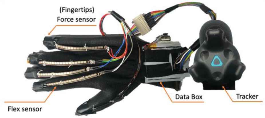
Data glove.
The Data box comprises of one Wemos D1 mini which is equipped with a WIFI module that allows us to implement the wireless data transmission, one ads1115 which can extend analog pin up to five pins including the A0 pin on Microcontroller Unit (MCU), and one customized Printed Circuit Board (PCB) with five 10k Ohms SMD resistors to minimize the box size as shown in Figure 2. Finally, we acquired the hand space position data through HTC vive tracker (HTC Corporation, Taiwan).
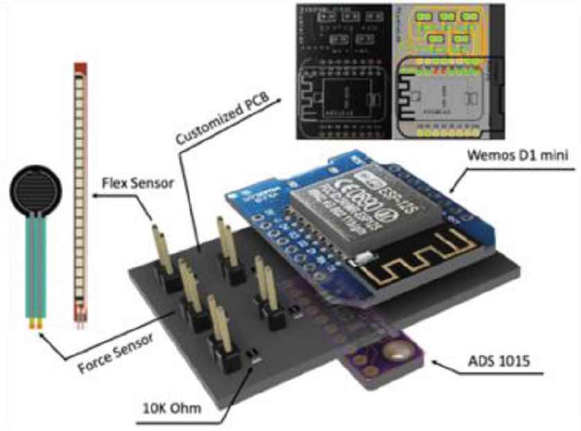
Inside data box.
A clear circuit layout as shown in Figure 3. The schema display that there’s an analog to digital signal converter connect with Wemos D1 mini and five analog sensors (force sensor or flex sensor). To minimize the circuit size, we adopt the 0805 SMD resistor to connect between sensor signal pin and Wemos D1 mini digital pin.
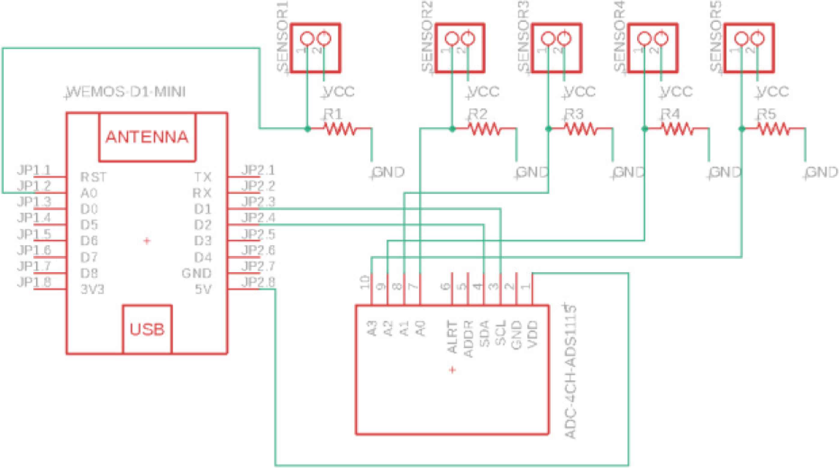
Data Glove PCB schema.
4. PRESSED DEFORMATION IMPLEMENTATION
To test the application of gloves to a variety of different shapes, we simulate the pressed deformation in Unity.
4.1. Force Direction
The experience we are trying to simulate is the deformation of the virtual object being pressed or poked by the user. This requires pushing the vertices near the collision point into the surface. In addition, we observed that the directionality of an applied force is diffusely applied to all directions. This will cause the vertices of the facade to be pushed away instead of moving inward.
For example, the poked point is (1,1,0), which means there is no Z-axis depth, that is of course, because we can only touch the surface of the object, but the force direction can be obtained through the normal point (0,0,−1). So when we add them together, it is (1,1,0) + (0,0,−1) = (1,1,−1). That is, if the depth change is multiplied by a force offset at the force spreading range, it can simulate the displacement range of each vertex after being pressed as shown in Figure 4.
Where Pd represents point with depth, Ppoked represents poked point and Np represents point along the normal line:
Then, we calculate each vertex with new depth as shown below, where i represents the total amount of vertex.
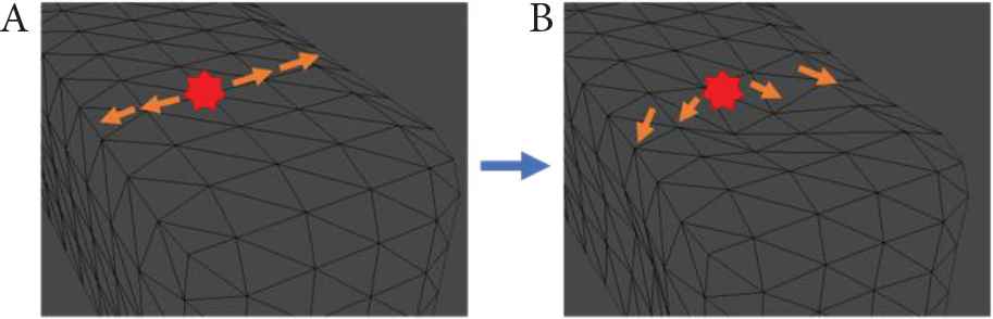
Force direction offset. (A) This represents the force direction before giving offset value. (B) This represents the force direction after giving offset value.
4.2. Add Force into Vertex Change
The mesh is deformed by an applied force. Over time, the deformation all changes vertices position as explained in the paragraph below. First, we need to know the distance between the poked point and mesh vertex.
Where i represents the amount of mesh vertices, D(i) represents the distance between the mesh point and hit point, XmV(i), YmV(i), ZmV(i) represent that mesh vertex on three axis, Pdx(i), Pdy(i), Pdz(i) represent Pd(i) value in three axis.
And we understand that the force effect will attenuate until zero with spread distance, and where we can adopt the inverse-square law as Equation (4). We add one plus the square D(i) to guarantee that the force is at full strength when the distance is zero.
Now that we have the attenuated force, we can convert it into a velocity delta. We know the Newton’s second law of motion F = Mass × Acceleration. And the deforming speed can be derived from uniform accelerated motion formula V = V0 + Acceleration × Time, where V0 is zero before object is poked. So, we can get Equation (5), where Tstep represents the frame time per second.
Then, we calculate each vertex velocity as shown below. Where Vmesh(i) represents the velocity of each mesh vertex and i represents the total amount of vertex.
Then, a vertex is updated to its deformed position, through Equation (7).
4.3. Stay in Shape
We have applied the attenuated force for each vertex. However, this change will not stop, and object has lost its original shape. We need to let the object bounce back to its original shape.
4.3.1. Spring effect
First, we need to get the distance between displaced state and original state. Where D(i) represents the distance, and Po(i) represents the original point.
Then, we assign Vmesh(i) a value that represents the mesh reflection speed of each point. Vfreq is used to represent the value of reflection frequency.
4.3.2. Damping
However, the reflection will continue and will not stop, so we need to give a constant CDamp as a damping property for the object to make sure the speed will decrease until it is stopped.
Then, we can feed the new Vmesh(i) back to Equation (7) to get the realistic deformation in a virtual environment.
5. BEND AND TWIST DEFORMATION IMPLEMENTATION
Object deformation not only has the pressed deformation, but also have the bend and twist deformation. We will explain how to implement them in this section.
5.1. Bend Deformation
In the beginning, we need to decide this object’s starting deformation point with lerp equation. However, the length and width in the virtual environment is symmetrical, so we can modify the equation as shown below. Where Pformed represents the start position, lwidth represents the mesh width and Pfrom is an input value from 0 to 1.
Then, we need to acquire and store each vertex from original vertex z(i) to Pformed. Here we use the value Pz(i) to represent the original mesh vertex point in the z axis alone.
Once we have the Dz(i), we can calculate each vertex angle of θ(i). Where θBend represents the input bending angle.
Now, we have each bending angle of each vertex, then we need to convert into radius to get the actual displacement value Dz(i).
We can update the Y coordinate value by adding the displacement of Dz(i) to get the correct y position.
We can also update the Z coordinate value by subtracting the Pformed to get the latest position after it is bent.
In the end, the latest updated position will be like as below:
5.2. Twist Deformation
Twist deformation is a typical deformation in physical objects. We will now explain how to implement this in a virtual object. In Equation (17), we can convert the input twist angle into an angle value. Where, φ represent the scale value which related to the size of virtual object.
We can then update the x position value by adding the correlation value of y and further update the y position by subtracting the correlation value of x to simulate the twist deformation on the virtual object. Since the twisting object will not affect the length of z, the z position is kept the same as the original value.
Finally, we can reveal these three deformation bases on the deformation algorithm as shown in Figure 5.
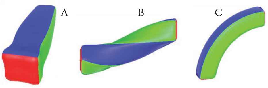
Rounded cube deformation: (A) pressed deformation, (B) twisted deformation, (C) bend deformation.
6. APPLICATION
To further illustrate the design space of the Data Glove, we developed three VR applications using Unity 3D, and loosely grouped them into three categories: (1) the illusion of pressing, (2) the illusion of bending, (3) the illusion of twisting. The application best demonstrates the VR glove’s unique capability of intuitive hand manipulation and rendering the haptic sensation of a highly dynamic and deformable object. As shown in Figure 6, the user can experience a variety of deformation illusions such as sponge and rubber with hand manipulation.
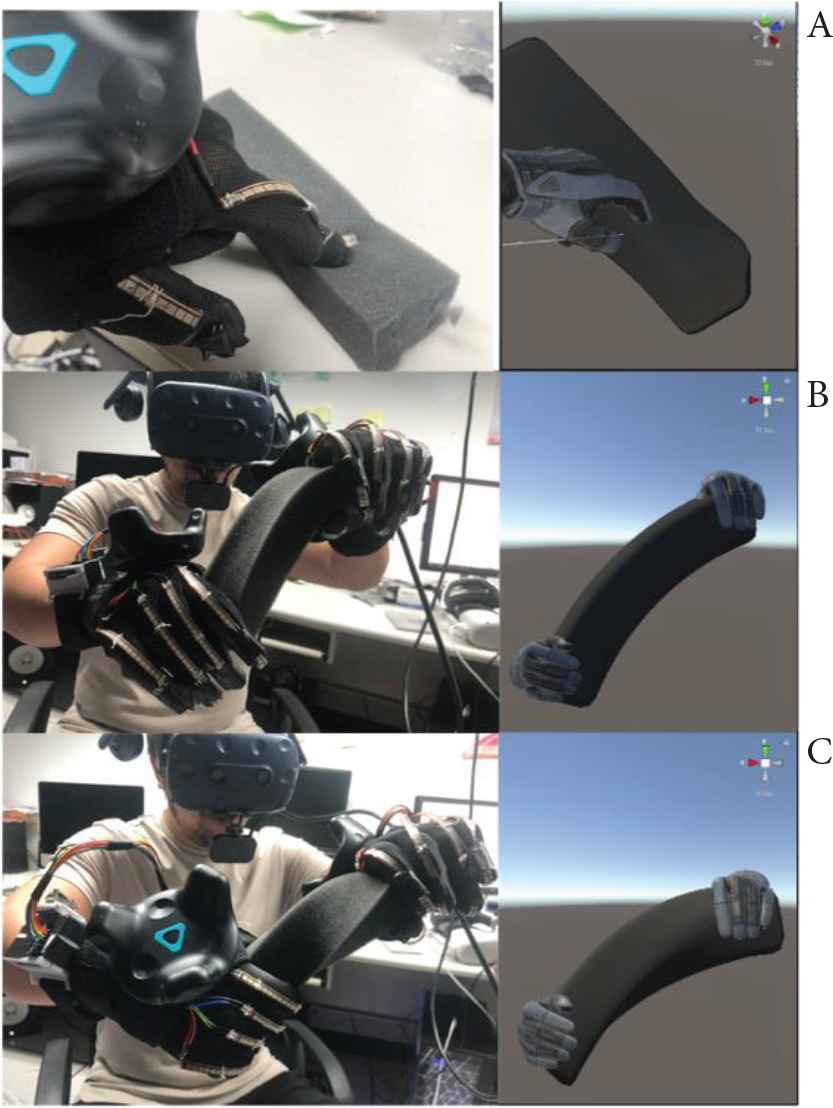
Demonstration of illusion deformation in between virtual and physical world. (A) The illusion of pressing, (B) the illusion of bending, (C) the illusion of twisting.
7. LIMITATIONS AND CONCLUSION
We see numerous areas of possible improvements to this VR Glove.
The main limitations are related to the precision of force detection and variety of object deformations in a virtual environment. Using five pressure sensors to render the deformation of a handheld object is a simple solution that comes with several trade-offs. The min–max ranges of detected force are limited, and in the case of pressing, the force is uneven depending on the direction of the fingertip.
The flex sensor is quite useful to detect the finger bending angle, but as we know, the finger consists of three bones, and the sensor can only detect the angle for the end bone, forcing us to stimulate the other two finger bone movements using math. In practice, more complex object deformation cannot be realistically rendered, and a polyhedron could make the deformation algorithm ineffective. This could be solved by, for example, using soft printable PCB technique which pastes force sensors and flex sensors into each key place on hand.
Furthermore, we expect that by adopting free-form surface deformation [19] and customized per-vertex stiffness map [20], we will be able to simulate deformation for a polyhedron in a virtual environment. Finally, the finger calibration method can occasionally generate value, creating an unrealistic sensation. Future work will explore various tasks that fit to everyday life as well as exploring the effect of different hand-held objects. Theoretically, the VR glove could be including multiple sensors to generate haptic feedback.
In conclusion, in this paper we introduced the VR glove, capable of creating the illusion of object deformation. We presented the overall hardware, PCB design and described how press, bend, and twist deformations can be simulated.
CONFLICTS OF INTEREST
The authors declare they have no conflicts of interest.
ACKNOWLEDGMENTS
The authors thank the Ministry of Science and Technology for financially and technically supporting this research in part under Grant MOST (IV) MOST 109-2218-E-002-038- and the project from National Taiwan University.
AUTHORS INTRODUCTION
Mr. Lee Jen Tun
 He received his master’s degree from the Department of Mechanical Design Engineering, National Formosa University, Taiwan in 2019. He is currently a Doctoral course student in Japan Advanced Institute of Science and Technology, Japan. His research interest includes human computer and robot interaction (HCI/HRI), Mixed Reality applications.
Dr. Janaka Rajapakse
 He is an Associate Professor at the Graduate Institute of Animation and Film Art, Tainan National University of the Arts, Taiwan. And he is also a visiting scholar in the Department of Media and Image Technology at the Faculty of Engineering, Tokyo Polytechnic University, Japan. He was a Postdoctoral Researcher at the Center for Hyper Media Research, Graduate School of Engineering, Tokyo Polytechnic University. He received his PhD in Knowledge System Science from Japan Advanced Institute of Science and Technology in 2008. His research interests include computer animation, motion capture, VR/AR/MR, haptic interfaces, AI, computer graphics, and Kansei Engineering. He is a member of the Motion Capture Society, The Society for Art and Science, ASIAGRAPH, and SIG- Design Creativity.
Dr. Kazunori Miyata
 He is a Professor at School of Knowledge Science in Japan Advanced Institute of Science and Technology. He received a PhD degree (Engineering) from Tokyo Institute of Technology, Japan, in 1996. His research interest includes computer graphics, media art, and multimedia applications. He is the 4th president of the Society for Art and Science, and a member of ACM, IEEE, IPSJ, IEICE, and others.
REFERENCES
Cite this article
TY  - JOUR
AU  - Lee Jen Tun
AU  - R.P.C. Janaka Rajapakse
AU  - Kazunori Miyata
PY  - 2021
DA  - 2021/12/29
TI  - HaptWarp: Implementation of Bend, Twist, and Press Manipulations for Intuitive Interaction in between the Virtual and Physical World
JO  - Journal of Robotics, Networking and Artificial Life
SP  - 263
EP  - 268
VL  - 8
IS  - 4
SN  - 2352-6386
UR  - https://doi.org/10.2991/jrnal.k.211108.007
DO  - 10.2991/jrnal.k.211108.007
ID  - Tun2021
ER  -