
Research of the Control Strategy of VIENNA Rectifier Circuit based on the Vector Control
- DOI
- 10.2991/jrnal.k.200512.003How to use a DOI?
- Keywords
- VIENNA rectifier; model systems; voltage imbalance; simulate; working principle
- Abstract
This paper analyzes the working principle of VIENNA rectifier and establishes the transformation model of rectifier in three different mathematical coordinate systems. First is to obtain the control structure of the converter, which is a double closed loop control structure (the voltage is the outer loop control and the current is the inner loop control). By using a feed forward control strategy to solve the problem of phase-to-phase coupling. By adding the voltage equalization loop and using the midpoint balance algorithm to solve the problem of the voltage imbalance caused by the rectifier under load. Finally, uses MATLAB to build the model, simulates and verifies the established model system.
- Copyright
- © 2020 The Authors. Published by Atlantis Press SARL.
- Open Access
- This is an open access article distributed under the CC BY-NC 4.0 license (http://creativecommons.org/licenses/by-nc/4.0/).
1. INTRODUCTION
Power electronic devices can be seen everywhere in our life. AC–DC rectifiers are common. Most rectifying devices adopt traditional rectifying methods, such as non-controlled rectifying circuit with diode and semi-controlled rectifying circuit with thyristor [1]. These topology structures generally have some shortcomings such as high current harmonics and low power factor. Due to the non-linear rectifying characteristics of rectifiers, a large number of harmonics and reactive power are injected into the power grid, causing serious interference to the power grid environment and reducing the power factor.
Therefore, how to solve the problem of harmonic and reactive power has attracted people’s attention. Reducing harmonic pollution to the grid environment is what every engineer and government want to do, so many industry standards have been developed. The most widely used are the ieee519-1992, iec555-2 and iec1000-3-2.
The application of PWM (Pulse Width Modulation) technology to control the rectifier makes the rectifier control simple and has excellent performance. At the same time the power grid side current sine and voltage in phase to ensure that the equipment in the unit power factor operation. VIENNA rectifier has two level relatives to the rectifier, the VIENNA rectifier output level increases in the number. Therefore, under the same bus bar voltage, the performance of low switch voltage stress, high power factor, low input current harmonics, high reliability, good features, make it become the hot research topic for the rectifier. Since the merits of the control strategy determines the performance of the rectifier, the VIENNA rectifier control strategy research has the important value of engineering application [2].
2. WORKING PRINCIPLE
The VIENNA rectifier is shown in Figure 1 with three-phase symmetrical AC input power supply and equivalent inductance on AC side. It plays the role of energy transfer in the rectifier, and can effectively suppress the high-order harmonics generated in the switching process and balance the voltage of each bridge arm and the grid input voltage. The capacitor on the output side of the DC bus with two identical parameters constitutes the tri-level structure. The rectifier has two fast recovery power diodes per bridge arm, so the rectifier needs six fast recovery power diodes. The rectifier also has three sets of bi-directional power switches. Because of the existence of the middle line, the three phases are independent of each other, and each phase can form an independent single-phase tri-level structure. In this paper, the three-phase three-wire topology is studied.
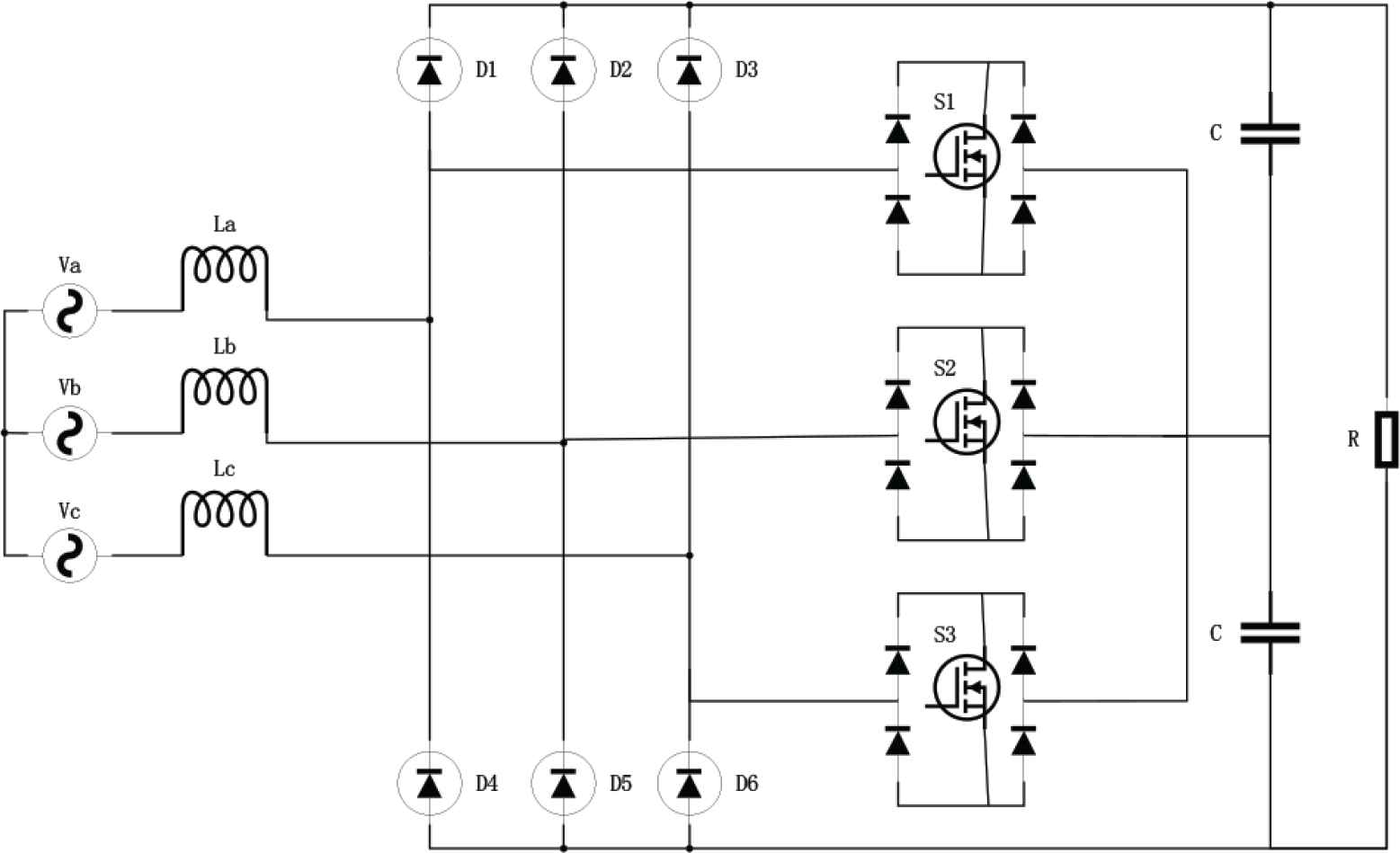
VIENNA circuit structure schematic diagram.
3. MATHEMATICAL MODEL OF VIENNA RECTIFIER
3.1. Mathematical Model in Three-phase Coordinate System
In order to achieve the best control performance, the circuit needs to be idealized. In the process of establishing the mathematical model of VIENNA rectifier, the following assumptions are made [3]:
- (1)
the sinusoidal voltage waveform of the three-phase AC input side of the rectifier is symmetrical;
- (2)
the power switching devices in the analyzed system are all set as ideal components;
- (3)
the switching frequency of the rectifier is much higher than the fundamental frequency of the AC input side;
- (4)
the upper and lower capacitance parameters of the DC bus side are the same.
Redefine the switching function, and set Sj (j = a, b, c) as the J phase function. The equivalent circuit diagram is shown in Figure 2.
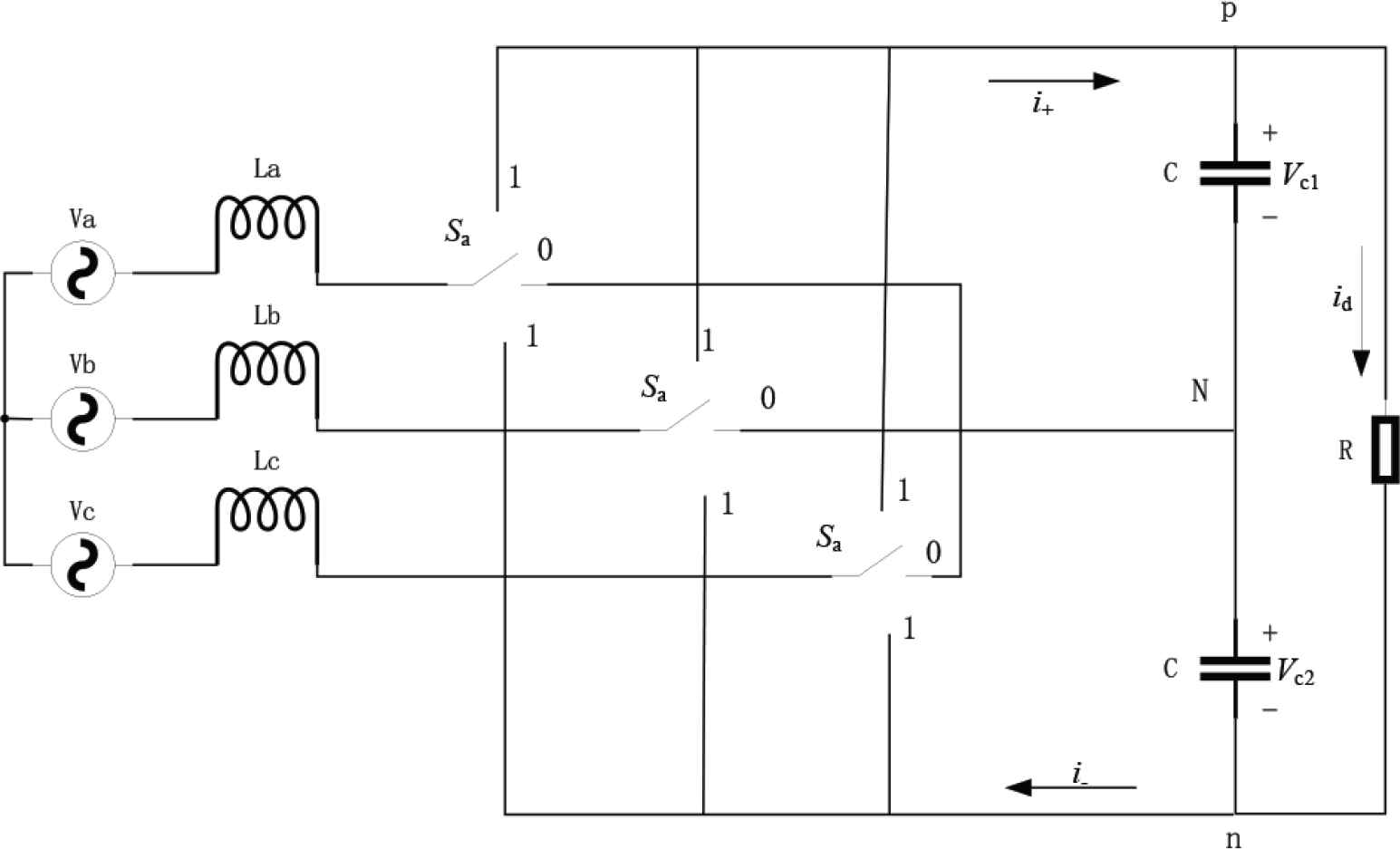
VIENNA circuit diagram.
In order to meet the three-phase power grid voltage symmetry, the mathematical model expression of the VIENNA rectifier in the ABC three-phase stationary coordinate system is obtained. It is known that the VIENNA rectifier is a multivariable, strongly coupled, high-order nonlinear system. The state equation of VIENNA circuit in the three-phase AC coordinate system can be expressed as:
3.2. Mathematical Model in Two-phase Coordinate System
The system is not easy to be controlled and the calculation is difficult. In order to simplify the control structure of the system, the coordinate transformation is carried out to obtain the synchronous rotating coordinate system. In this coordinate system, it is easy to calculate the direct flow. Let d-axis in d − q coordinate system and a axis in ABC three-phase coordinate system be in the same direction, so the included angle is 0. The transformation of coordinate system is divided into two stages: (1) the transformation of ABC-αβ coordinates. (2) the αβ-dq coordinate transformation. Figure 3 shows the transformation matrix from the three-phase AC static coordinate system to the two-phase AC static coordinate system [4].
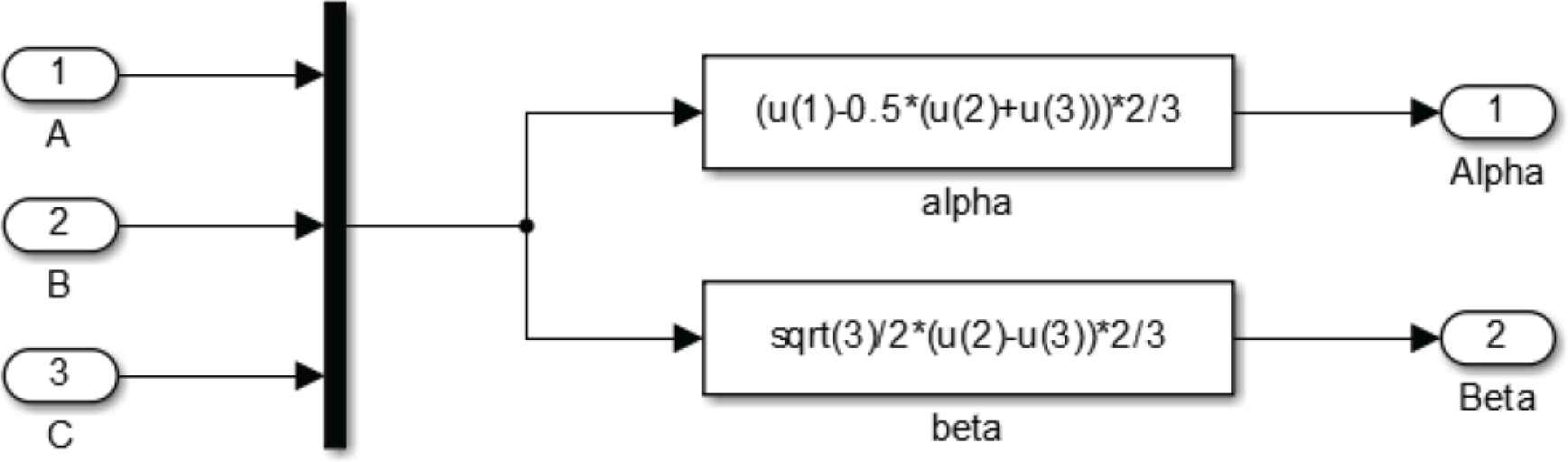
Clark transformation matrix.
The ABC-αβ transformation can be expressed as:
3.3. Mathematical Model in d − q Coordinate System
The αβ-dq transformation can be expressed as:
In the formula, wt is the output phase.
The αβ-dq simulation model is shown in Figure 4.
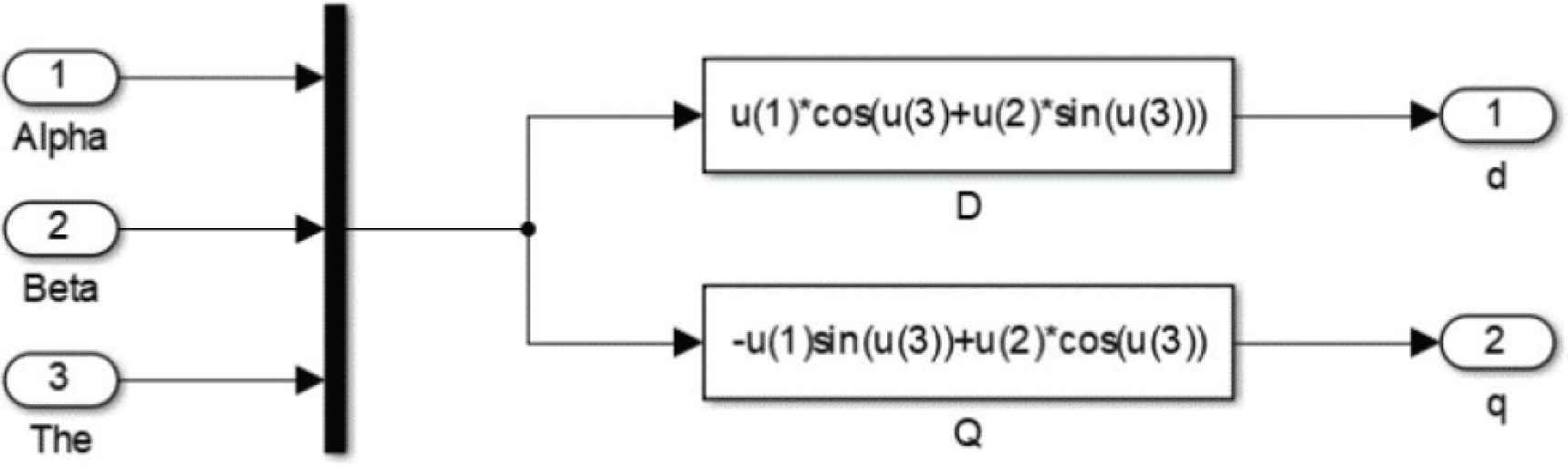
The αβ-dq simulation model.
4. SYSTEM SIMULATION OF VIENNA RECTIFIER
4.1. Open-loop Simulation of VIENNA Rectifier
In the process of designing the open loop control system, the system controller and the controlled object should be considered. The controller generates the control signal to the controlled object to achieve the expected function. The open-loop system is a relatively basic control system. First, the open-loop circuit of VIENNA rectifier is built to verify the feasibility and anti-interference ability of the system, so as to draw the difference between open-loop control system and closed-loop control system. As can be seen from Figure 5a and 5b, stable voltage and current output can be achieved when there is no interference in the system. When there is interference in the system, the output of the open-loop system with sudden load reduction has a distinct jump, and there is no way to restore to the set value, so the anti-disturbance ability of the open-loop system is poor.
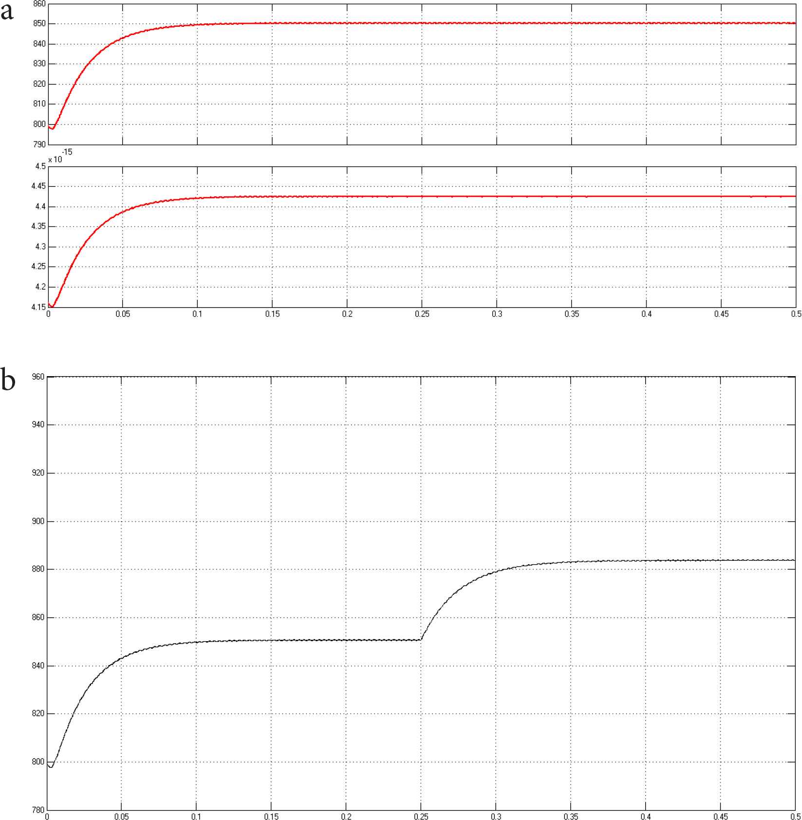
(a) VIENNA rectifier open-loop steady state voltage (upper) and current output (lower). (b) Perturbation in an open-loop system.
4.2. Closed-loop Simulation of VIENNA Rectifier
The control scheme is verified by simulation and experiment. As long as the control parameters are calculated correctly, the circuit performance can meet the specified requirements.
Simulation parameters of the main circuit system are as follows: switching frequency fs = 10 KHz; Inductance value La = Lb = Lc = 10 mH; Stabilized voltage filter capacitor C1 = C2 = 2200 μF.
Figure 6a and 6b are respectively the DC side voltage simulation waveform and the three-phase input voltage and input current simulation waveform of the VIENNA rectifier in steady-state operation. The AC input voltage Va = Vb = Vc = 220 V, rectifier at full load, load impedance load for R = 72 Ohms, VDC+ = VDC− = 425 V.
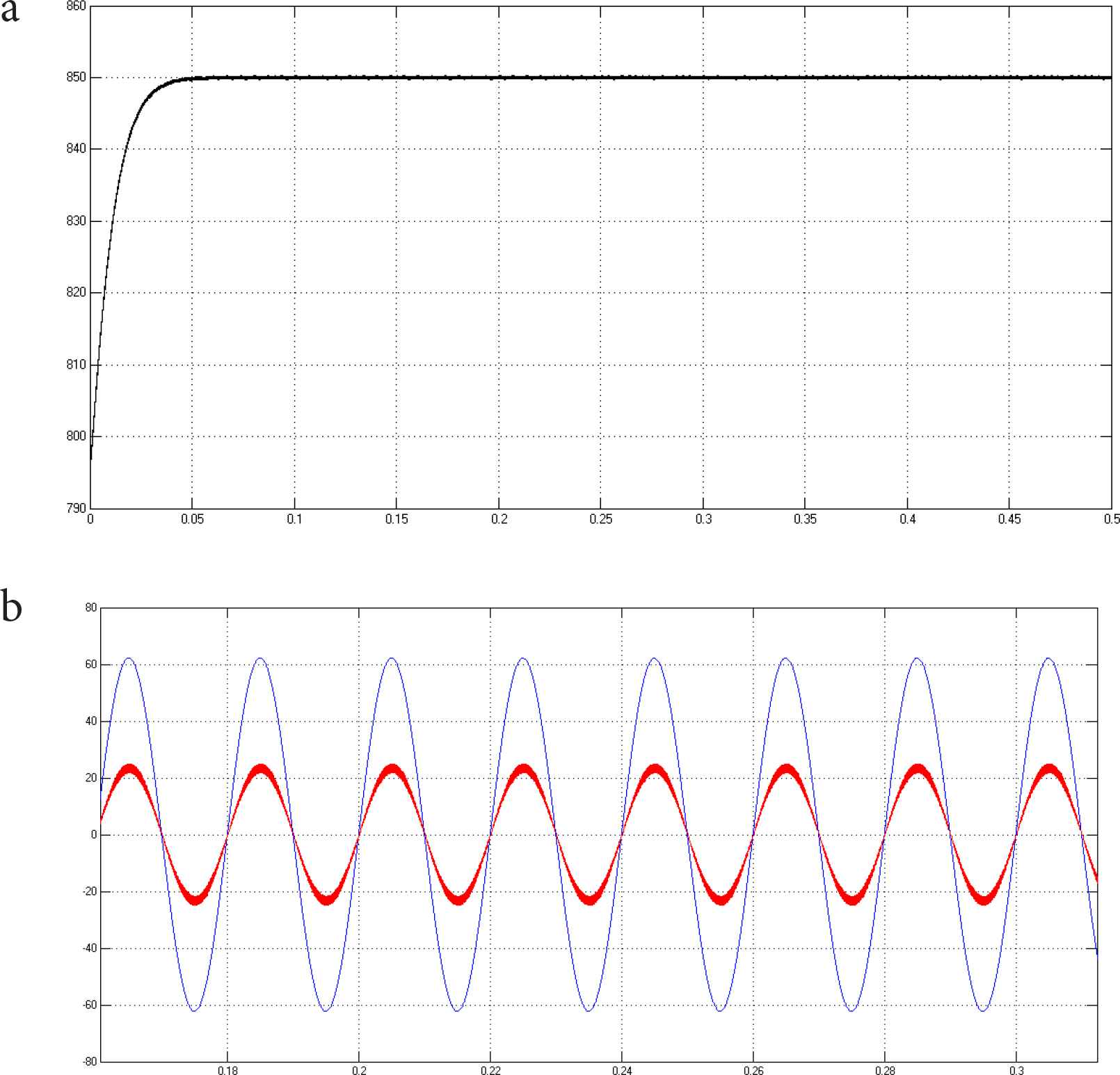
(a) DC side voltage waveform. (b) The steady-state waveform.
4.3. Simulation of Mutation Load
In order to verify the reliability of the system and the ability to suppress the load variation, the simulation of load abrupt addition and abrupt subtraction was carried out in the built simulation model, and the waveform change of voltage and current on the AC side and voltage on the DC side was observed (Figure 7a and 7b).
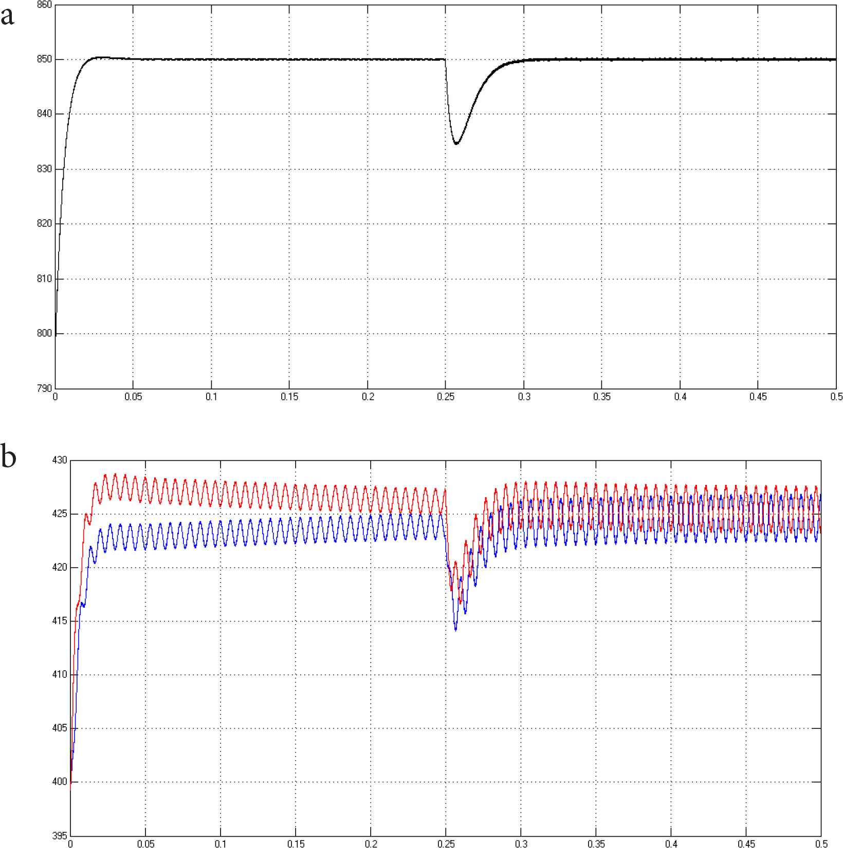
(a) Output voltage waveform applied by load. (b) Output capacitance voltage waveform applied by load.
CONFLICTS OF INTEREST
The authors declare they have no conflicts of interest.
ACKNOWLEDGMENTS
This research is partly supported by the Project of Tianjin Enterprise Science and Technology Commissioner to Tianjin Tianke Intelligent and Manufacture Technology Co., Ltd (19JCTPJC53700). It is also supported by the Industry-University Cooperation and Education Project (201802286009) from Ministry of Education, China.
AUTHORS INTRODUCTION
Dr. Fengzhi Dai
 He received an M.E. and Doctor of Engineering (PhD) from the Beijing Institute of Technology, China in 1998 and Oita University, Japan in 2004 respectively. His main research interests are artificial intelligence, pattern recognition and robotics.
He worked in National Institute of Technology, Matsue College, Japan from 2003 to 2009. Since October 2009, he has been the staff in Tianjin University of Science and Technology, China, where he is currently an associate Professor of the College of Electronic Information and Automation.
Ms. Yuxuan Zhu
 She is a second-year master candidate in Tianjin University of Science and Technology. Her research area is about machine learning, big data analysis.
Ms. Di Yin
 She is a second-year master candidate in Tianjin University of Science and Technology, majoring in brain-computer interface, machine learning.
Mr. Yasheng Yuan
 He is a second-year master candidate in Tianjin University of Science and Technology. His research area is about deep learning, Internet of things.
REFERENCES
Cite this article
TY  - JOUR
AU  - Fengzhi Dai
AU  - Yuxuan Zhu
AU  - Di Yin
AU  - Yasheng Yuan
PY  - 2020
DA  - 2020/05/14
TI  - Research of the Control Strategy of VIENNA Rectifier Circuit based on the Vector Control
JO  - Journal of Robotics, Networking and Artificial Life
SP  - 12
EP  - 15
VL  - 7
IS  - 1
SN  - 2352-6386
UR  - https://doi.org/10.2991/jrnal.k.200512.003
DO  - 10.2991/jrnal.k.200512.003
ID  - Dai2020
ER  -