
Feasibility Study of UAV Implementation in Route Surveying
- DOI
- 10.2991/jrnal.k.190828.003How to use a DOI?
- Keywords
- UAV; engineering work; land survey; drone
- Abstract
Unmanned Aerial Vehicle (UAV) are widely used in numerous field and the technology keeps growing. Generally, conventional method used in data collection for engineering work is tedious and requires a lot of manpower. This research focuses on the investigation of the suitability of UAV for route survey. Three stages involved: data collection, data processing and data analysis. By using Kama Beta, the data was collected. For data processing, Pix4D Mapper is used for point cloud and AutoCAD 2014 for the analysis stage. The result is mainly focused on extracting the road profile and test the point cloud data using Root Mean Square Error (RMSE). The result from both methods, conventional and UAV from the point cloud data using RMSE show only the small difference, with only 6.67% from total 60 points out of tolerance.
- Copyright
- © 2019 The Authors. Published by Atlantis Press SARL.
- Open Access
- This is an open access article distributed under the CC BY-NC 4.0 license (http://creativecommons.org/licenses/by-nc/4.0/).
1. INTRODUCTION
Engineering survey is a survey undertaken for the purpose of obtaining information essential to the planning of an engineering project. Engineering survey provides accurate and reliable dimension data through the construction process from the base topographical survey, cross-section and ground modelling information to cut and fill calculation, dimensional control to setting-out on-site and finished as-built drawing [1].
Route surveying is comprised of all survey operation required for designing and construction of engineering works such as highways, pipelines, canals or railroads. Survey operations in route survey include topographic survey, cross-section and longitudinal section [2].
Unmanned Aerial Vehicles (UAVs), also known as “drones”, are among the most important technological advances that have been introduced to the land surveying industry in quite some time. It can be piloted by remote and can take detailed survey information while simultaneously transmitting that data back to the head office. UAVs create a highly accurate map and provide valuable data to companies and individuals who are considering major projects on large areas of land. Research about the reliability of these techniques to be used in topographic mapping was conducted in land survey method [3].
2. METHODOLOGY
2.1. Planning and Preparation
Planning and preparation are needed before the data collection. Planning and preparation cover the scope of work such as planning for the area of the survey and the preparation for the instrument and software used in this project. Good planning and preparation enable to ensure efficiency and maintaining a high quality of the data collection in this study. Furthermore, proper planning and preparation help in saving time and cost as time increase, the cost will increase as well.
2.2. Data Collection
Data collection for this study is focused on two methods. The first method of data is used as a conventional method by total station. Besides that, the second method for this study used a new method by UAV.
2.3. Data Processing
Data processing for this study refers to process the laser and the conventional method. Data processing for a conventional method uses the Civil Design & Survey software. Besides that, for the UAV processing used Pix4D Mapper. Both use AutoCAD as data analysis processing.
3. RESULTS AND ANALYSIS
3.1. Camera Calibration
The camera calibration is done before doing the flight planning. The purpose of camera calibration is to determine the focal length, principal point, and lens distortion from the camera. This process was carried out to figure out the unstable element in the camera like interior orientation and lens distortion parameters [4].
In this project, the camera calibration is processed using PhotoModeler Software. This software is an automatic lens calibration, which uses A1 paper sheet as a calibration target. It supports estimations of the full camera calibration matrix, including non-linear distortion coefficient.
To check the accuracy of the camera calibration results, the total final error must be checked. In both methods, the data sets are not the same. For lab calibration, the data set is the grid of the pattern and for filed calibration are the 67 targets points. According to PhotoModeler tutorial, a value <1.0 pixel indicates a good calibration and very good calibrations can have a final total error smaller than 0.4 pixels (www.photomodeler.com). In this case, the lab calibration has a final error of 1.940 pixels [7].
The total error was a bit higher than the recommended. The field calibration has a total error of 0.282 pixels, which is assumed to be a very good calibration project. Also checking the marking residuals is a good way to test the calibration quality [4]. PhotoModeler tutorial recommended having the largest marking residual <1.0 pixel [3]. In both cases, the largest marking residuals are <1.0 pixel. The lab calibration has 0.723 pixels and the field calibration 0.700 pixels (Table 1).
| Lab calibration | Field calibration (50 m flight high) | |
|---|---|---|
| Final total error (pixel) | 1.940 | 0.282 |
| Largest marking residual (pixel) | 0.723 | 0.700 |
| Overall RMS (pixel) | 0.245 | 0.341 |
Total final error and residuals of the camera
The accuracy of field calibration was also checked to compare the Global Positioning System (GPS) coordinates of the targets with the coordinates obtained with PhotoModeler. This software only needs three control points to change from relative to absolute coordinates. For this process, the targets number one, two and four were used. The planimetric and the altimetric Root Mean Square (RMS) were calculated. The planimetric RMS was 0.028 m and the altimetric 0.026 m, which is really small and indicates the accuracy level of the project [7].
3.2. Georeferencing
Ground Control Point (GCP) and Verification Point (VP) are very important data that are used to involve in aerial triangulation phase, where it can be identified on the ground features and can be georeferenced with the aerial image used in geometric correction of the distorted image [3]. Therefore, pre-marking for GCP’s and VP’s must be carried out before a flight mission. This is because the processing of the tie point image could be more efficient and accurate. The coordinates of x, y and z-value that were observed using levelling method (land survey).
Figure 1 shows the strategic location of placement six (6) GCP’s. The location of GCP was in Chuping, Perlis, Malaysia. Each of GCP is observed by GPS equipment (Topcon – GR5) using Static Method. The reason of this method selection is because this method is the most widely used differential technique for control and geodetic surveying, involved 1 h of observation to resolve the integer ambiguities between the satellite and the receiver. By using this method, the accuracies in the sub-centimeter range can be obtained.
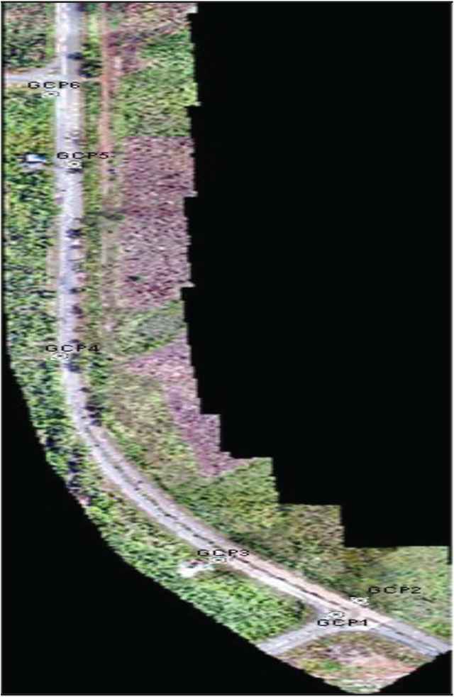
Location of GCP in UAV images in Chuping, Perlis, Malaysia (Orthophoto).
3.3. Digital Surface Model
The aerial image was taken from above with 14 min flight duration. To achieve this project the overlap is 80%, sidelap is 70% and the altitude is 110 m. This overlapping and flight altitude is required to avoid potential missing areas of coverage and to ensure good coverage. Based on the data that has been processed using Pix4D software, produced an Orthophoto and Digital Surface Model (DSM) in raster as shown in Figures 1 and 2.
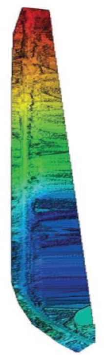
DSM of the project area (Location: Chuping, Perlis, Malaysia).
Figure 3 shows the sample result road profile of UAV and TS data for CH 1 to CH 10, which is located in Chuping, Perlis, Malaysia. Based on Figure 3, the red color refers to the highest elevation while the soft blue color refers to the lowest elevation [5]. Therefore, it can clearly be seen that the UAV data gives a greater number of point compared with TS data. Besides that, the profile generated by using UAV is denser than the TS data due to the great number of point [6].
RMSE error verification points.
3.4. Statistical Analysis
The road profiles are tested with RMS Error (RMSE) which is done by analyzing the comparison of differences between and within the group. The road profile is statistically tested by using the RMSE test at each chainage to ensure that the data of UAV and TS is significant to each other.
Root mean square error is the standard deviation of the residuals (prediction errors). Residuals are a measure of how far from the regression line data points are; RMSE is a measure of how to spread out these residuals are. In other words, it tells you how concentrated the data is around the line of best fit. RMSE is commonly used in climatology, forecasting, and regression analysis to verify experimental results [5].
The formula (1) is:
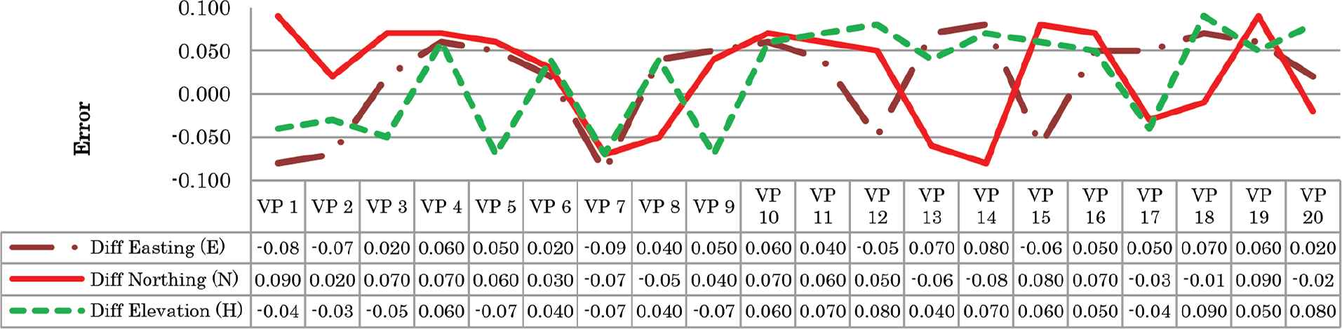
There are three types of sample tested using RMSE formula, verification point, positioning and elevation. Values from the real measurement are compared with the value from the 3D modelling to get the error of every sample.
Based on Figure 3, it can be seen that the graph values of RMSE VP are for minimum and maximum errors. All the VPs are under tolerance which is below ±0.10 m. Based on Figure 4, it can be seen that the graph values of RMSE Cross Section are for minimum and maximum errors are for Different Elevation (H). The best result is ±0.03 m (VP5). VP9, VP10, and VP18 are out of tolerance which is above ±0.10 m.
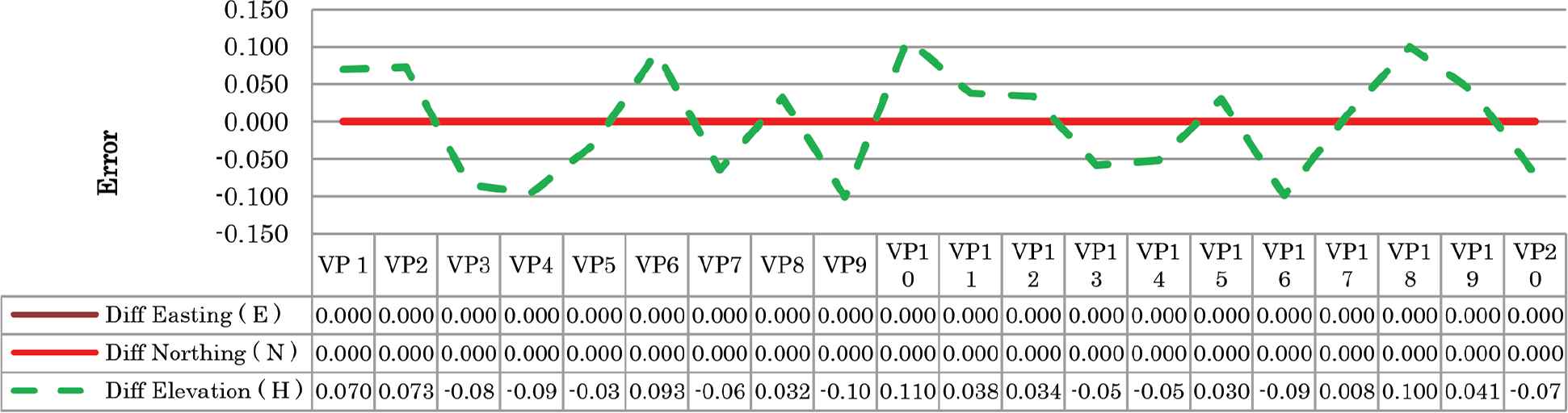
RMSE error cross-section.
The values of RMSE XY for minimum and maximum errors can be referred to Figure 5. All the XY are under tolerance which is below ±0.10 m except at VP19 with value ±0.125 m. These results might be affected by image matching algorithm that was used in the same software during image processing. The error was usually caused by flying height during image acquisition, image matching during image processing and motion movements such as ω, π, and κ [6].
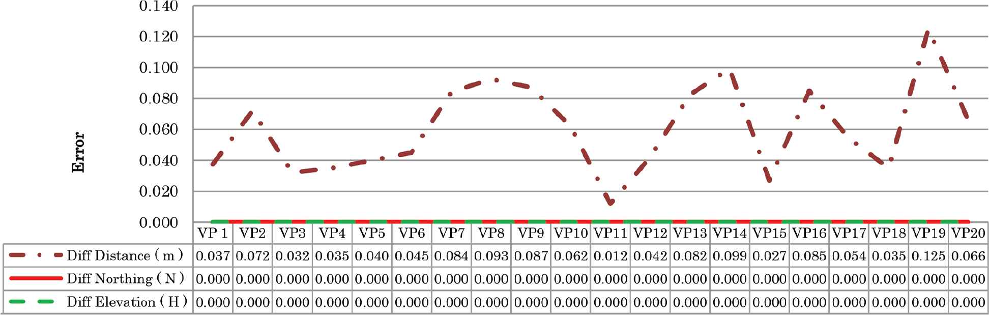
Residual error XY.
4. CONCLUSION
As a conclusion, the three objectives of this study has been achieved. The first objective is to process image capture from UAV. The most important procedure for route survey work is data collection. Planning and preparation in this study focusing on planning for a number of GCP and flight planning. Number of GCP depends on a number of flight planning where need minimum visible from the aerial view and location of GCP. After that, the procedure for route survey by using UAV need to focus on processing the point cloud data. Starting with data registration point cloud data uses minimum of three images that visible each other. Then, the next process is point cloud densification using PIX4D Mapper software. Then, the next process produces DSM and Orthophoto. In this research, two methods were applied, land survey and UAV survey.
A land survey is used as a benchmark for this research. Point cloud data produce in 2D data with 3D coordinate which can use to generate road profile for route survey. The third objective for this study is to analyse the accuracy between land survey data and UAV data. Series of test and analysis have been conducted in terms of the reliability of UAV data in completing a route survey. The reliability of UAV data shows in quantitative assessment by comparing result road profile from UAV and TS method.
CONFLICTS OF INTEREST
The authors declare they have no conflict of interest.
ACKNOWLEDGMENTS
The author acknowledges International Conference on Artificial Life and Robotics (ICAROB) for giving the opportunity to join this conference. High appreciation to UAS research team for excellent contribution. Special gratitude to IP Fokus Sdn Bhd for full support in completing this project.
Authors Introduction
Prof. Ts. Dr. Hazry Desa
 He is a Director of Center of Excellence for Unmanned Aerial System at University of Perlis (UniMAP). He has published many publications and filled patents on the application of UAV for crop spraying and monitoring. He leads the educational program and organized several UAS related conference in Malaysia. He is a member of IEEE.
Mr. Ts. Muhammad Azizi bin Azizan
 He received his MSc degree from University of Technology Mara (UiTM) in Integrated Project Management. He is a Non-Executive Group Director, Aurum Group and Vice President (Malaysia Global Economic Chamber of Commerce). Registered as CIOB UK, CIBSE UK, HRDF Malaysia and RISM Malaysia. Nature of research are Property, Construction, Consultation, Manufacturing and Supply.
Mr. Mohamad Syafiq Abdul Khadir
 Graduated in MSc in Mechanical Engineering, form UniMAP. Currently, works as a lecturer in Faculty of Technology Engineering, Mechanical Department. Interested in UAS, Heat Transfer, Automotive and Green Technology.
Mr. Muhammad Safwan Suhaimi
 Graduated from UiTM Arau in 2014. Works as Geospatial Engineer and Research Assistant under Center of Excellence for Unmanned Aerial System (COEUAS) UniMAP.
Noor Zulaiha Ramli
 Graduated from UiTM Arau in 2014. Works as Geospatial Engineer and Research Assistant under Center of Excellence for Unmanned Aerial System (COEUAS) UniMAP.
Mr. Zainudin Hat
 The owner of IP Fokus Sdn Bhd Actively involved in research for Unmanned Aerial System (UAS), Building surveying and Construction
REFERENCES
Cite this article
TY  - JOUR
AU  - Hazry Desa
AU  - Muhammad Azizi bin Azizan
AU  - Mohamad Syafiq Abdul Khadir
AU  - Muhammad Safwan Suhaimi
AU  - Noor Zulaiha Ramli
AU  - Zainudin Hat
PY  - 2019
DA  - 2019/09/10
TI  - Feasibility Study of UAV Implementation in Route Surveying
JO  - Journal of Robotics, Networking and Artificial Life
SP  - 84
EP  - 88
VL  - 6
IS  - 2
SN  - 2352-6386
UR  - https://doi.org/10.2991/jrnal.k.190828.003
DO  - 10.2991/jrnal.k.190828.003
ID  - Desa2019
ER  -