
Handoff Delay Optimization Using Hybrid Prediction Model
- DOI
- 10.2991/ijndc.2018.6.2.5How to use a DOI?
- Copyright
- Copyright © 2018, the Authors. Published by Atlantis Press.
- Open Access
- This is an open access article under the CC BY-NC license (http://creativecommons.org/licences/by-nc/4.0/).
1. Introduction
In cellular network, a geographical area is divided into cells that are aggregated into groups called Location area (LA). For delivering services to a user, all the cells in an LA covering the user will be paged to establish the radio link connection. Within the LA, frequencies used in one LA can be used in another LA. Arrangement of large number of cells per LA reduces interference to the system [4]. Each cell has its own cellular tower called base station (BS). Several base stations are under the control of a Base Station Controller (BSC) that comes under a mobile switching center (MSC) [2]. Each MSC belongs to a data base called visitor location register (VLR). VLR assigns a temporary mobile subscriber identity to every mobile station (MS) in the area and hence it has to be updated each time when the MS travels from one cell to another.
1.1. Cellular Network Architecture
As indicated in Fig. 1, in cellular networks, the system keeps track of the location of an MS through an up-to-date profile of it stored in various databases namely VLR and Home Location Register (HLR). An MS profile consists not only of its current location information, but also service information, such as billing and authentication.
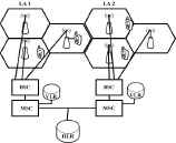
Cellular Network Architecture
The tremendous usage of smart phones and electronic tablets has increased the explosive growth of multimedia wireless services. To improve the network performance, an efficient location management is essential. Location management handles and keeps track of an active MS within the cellular network. Since while making a call, the exact location of an MS has be known to the network, the location management usually tracks an active MS between two consecutive phone calls [3].
In a cellular network, Mobile Movement Prediction is defined as the prediction of the next movement of the MS in a networked environment [25]. The MS can access the network services while moving from one location to another. Although, a wealth of information is available on Mobility Management to store and update the location information of mobile stations which are served by the system, limited studies have been done in the area of location prediction. The present study centers around two aspects. The first involves determination of the least distance of a BS from the MS, while the second helps to delineate the congested and non-congested BSs. From the above findings, one can predict the next location of MS by which the handoff delay is optimised.
2. Related Works
In [7], authors introduced a hybrid UTDOA and AGPS positioning technique in mobile network and developed a novel future location prediction algorithm. ICMP consists of three levels of prediction viz. cell-to-cell, sector-to-sector and intra-sector predictions. The achieved algorithm ICMP provides the requirement of future prediction of mobile stations location which helps to enhance both LBS based on mobile network operators and mobile network allocation resources.
A simple Multi Layer Perception (MLP) model which is able to resolve non-linearly separable problems was described by authors in [8]. To build a multilayer perception, a number of neurons are connected in layers where each of them is able to identify small linearly separable sections of the inputs and is used to get the final output in the network. They found that the regular and uniform pattern can be extended for random data as well.
In [9], authors suggested a prediction algorithm that aimed at reducing handoff latency by minimizing the frequent switching between the base stations with respect to movement of mobile stations. They focused on reducing handover-related issue by using location-based information.
A predictive mobility and routing management scheme using the movement circle and movement track models as well as the Markov chain model was developed by authors in [10]. They developed a class of mobile motion prediction algorithms which consisted of two algorithms: regularity-pattern detection algorithm and a motion prediction algorithm for supporting services pre-connection, routing pre-arrangement and resources pre-allocation. The algorithm, in practise, was simple and fast.
In [11], authors integrated a Protocol for Carrying Authentication for Network Access (PANA) by which an Enhanced Secure Handoff (ESH) algorithm is designed to optimize inter-domain and inter-technology handoff. They also designed a fast roaming algorithm to provide secured roaming. A single handoff procedure between the inter-domain and inter-technology replaced the number of handoff procedures between several APs and users in ESH algorithm.
A novel handoff decision strategy, including the network selection algorithm for originating calls and the vertical handoff decision algorithm for vertical handoff calls, in overlay wireless networks, was designed by authors in [12]. Unlike most previous vertical handoff decision strategies which were designed to meet individual needs, the handoff decision was made by their system.
In [13], authors presented the user pattern learning approach6 by using neural networks to reduce location update signalling cost by increasing the intelligence of the location procedure. This approach associated to each user a list of cells where mobile is likely to be with a given probability in each time interval. The list was ranked between the most likely and the least likely place where a user might be found. When a call arrived for a mobile, it was paged sequentially in each location within the list.
3. Mobility Management
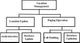
Mobility management is critical in cellular network that provides services to MSs. It includes two operations: Location and Handoff management. Location management activates call delivery to MSs, while handoff management maintains the connectivity of ongoing calls [16].
3.1. Location Management
Mobility management involves the tracking of mobile nodes irrespective of their present location. There are two basic operations namely, Location update and Paging which are handled by the network. When a call arrives for an MS, the cellular network pages the MS in all possible cells to find out which cell the MS is located and the incoming call is routed to the corresponding BS. The number of paging cells is dependent on how the location update operation is performed [3].
3.1.1. Cost components
The cost components of Location management are illustrated in Fig. 2 and can be calculated by a simulation process. The average cost of location management can be determined using the following equation [5].
Cost Components
Here, NLU is the number of location updates and NP is the number of paging performed during time T. C represents a constant which is the cost ratio of location update and paging.
3.1.2. Location Update
Location update is the process by which the mobile network is informed about the location of an MS. For updating the new location, MS is required to register with the current BS to allow the incoming and outgoing calls. Each location update is a costly exercise because it needs the cellular network bandwidth, core network communication and location database update [14].The process of location update is done by an active MS. For example, in Fig. 3, the mobile station MS1 moves from one cell to the next, which is covered by the base station BS2. The MS1 now requires to be registered with the BS2.
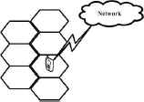
Location Update
3.1.3. Paging
Paging is a process in which mobile network searches and finds an MS when a call is directed towards it. The network should then find the location of the MS to forward the incoming call to that MS. Generally paging is done by the network by sending queries to the cell in which the MS is located. As shown in the Fig. 4, all MSs located in that LA listen to that query and only the one that is called would reply back.
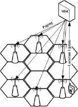
Paging
Generally the location update is done by an MS while paging is done by the network. The number of all possible cells to be paged is dependent on how the location update operation is performed [15].
3.2. Handoff Management
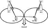
In handoff management, an MS is able to connect the next BS only by maintaining its connection with current BS while it is moving from one cell to another [17]. Each cell in the cellular network is capable of providing telecommunication services to MSs roaming with them. Each cell can only serve up to a certain geographical area and a specified number of MSs. Handoff happens when an MS surpasses any of above two limits.
When an MS travels from one cell to another, a handoff takes place between the two cells. All services provided by the previous cell are transferred to the target cell when handoff takes place. A hand-off becomes automatic when the number of MSs in a particular cell has already reached the maximum capacity of a cell.
Handoff Management
To maximize the spectrum utilization of the cellular architecture, handoff mechanism is extremely important in cellular networks. As an MS moves through the coverage area of the cellular system, handoff transfers an ongoing call from one cell to another [18]. While an MS switches between cells, an efficient handover mechanism and location prediction method improves the performance of cellular network. In the present study, a new algorithm is proposed which can optimize handoff delay and predict the new location of MS.
When an MS is travelling and attending to a call simultaneously, in the present scenario, a network cannot clearly identify the exact location of the MS using running GPS application. However, it can identify the BS where the MS is located. The current proposal describes an algorithm which discusses the functionality of GPS module in the SIM of MS.
3.2.1. Optimization of Ping-Pong Effect
Handoffs that occur back and forth between two BSs are often referred to as ping-pong effect [21]. It severely affects both user’s quality perception and the network load. In this paper, location prediction optimizes this problem because location is predicted well in advance so that MS can locate the predicted BS directly.
4. Proposed Architecture
Mobile phone tracking is one of the biggest issues in recent times involving privacy concerns for people. Many are uncomfortable with their location being tracked at all times by known or unknown sources. It can also lead to deception, interference in social life and security issues for famous personalities [22].
To overcome this issue, the present paper puts forward an innovative idea which does not involve the tracking of an MS by others. MS with GPS integrated SIM can only be tracked by the network at all times but not by others. Fig 6 illustrates the components that exist in the proposed network and includes wired and wireless connected components. Further, in this system, a new component namely, Prediction server (PS) has been introduced to store the current location details of all MSs located under it in a continuous fashion. This prediction server is located along with each MSC and each MSC has a PS in this network.
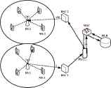
Proposed Architecture
During the movement of an MS with GPS integrated SIM, specified details like LA-ID, BS-ID, BS-Latitude, BS-Longitude, MS-ID, MS-Latitude, MS-Longitude, DATE-Of-Registration, TIME-Of-Registration are stored after a specified time interval in the PS through the corresponding BSC. When the MS is switching from one cell to another, the above mentioned details are collected by a PS. Using the saved historical data, the PS can determine the non-congested BS among the all BSs available under its control.
4.1. Steps for establishing a connection request from MS1 to MS2
- (i)
Connection request from BS1 to BSC1 for MS1
- (ii)
BSC1 hands over the request to PS server.
- (iii)
Request is now passed on to MSC
- (iv)
MSC puts a query to HLR for checking the profile of MS1.
- (v)
HLR finds the profile of MS1 and gives reply to MSC.
- (vi)
MSC gives acceptance to PS.
- (vii)
PS handsover that acceptance to BSC2.
- (viii)
BSC2 passes the location details of MS1to BS2. Then connection is established between MS1and MS2.
4.2. Location Finding
In the current scenario, a given network has only the capacity to find the location of a BS where an MS is placed. Unfortunately, it is unable to find the current location of the MS [19]. But in the current proposal, the above mentioned location details are collected by the PS after a fixed time interval. Every time the PS is vigilant about the current locations of all the MSs existing under all BSs which are residing at current PS. While MS is moving from one cell to another, handoff takes place and is handled by the PS.
4.3. Handoff Management in the Proposed Architecture
In the current scenario, when an MS is moving from one location to another, it is registered in the VLR and in this case, it acts as only a storage device [20]. But in the present study, VLR is replaced by an intelligent storage device PS where all the details from every MSs through BSC are stored in the PS. Being an intelligent device, PS gives information about the entry of a new incoming MS to MSC. MSC then picks the permanent details from the HLR and permits the entry of the new MS to the new BS via PS and BSC and handoff of MS then takes place.
4.4. Establishing Connection
In a GSM cellular network, MSC locates an MS from VLR. After gathering the required location details of MS from VLR, the MSC broadcasts a page request to all BSs that come under the specified LA through BSC [20]. Then MS responds to the page request and BSC allocates a traffic channel and sends a message to the MS to tune to the channel. The MS generates a ringing signal and after the subscriber has answered, the speech connection is established. Contrary to the above, in this proposed network, when a request from a caller MS transfers to PS through BSC, it handovers that request to MSC, MSC finds out the permanent details of the called MS from HLR. After the confirmation from HLR, MSC informs PS to accord permission for further procedures. Then PS sends the acceptance message to BSC which passes it to BS and MS. Thus a new connection is established. Here, MSC is not required to collect the details from VLR and thus establishment of connection is handled smoothly.
5. Methodology
A powerful technique which is used for predicting the unknown value of a variable from the known value of another is referred to linear regression. This method consists of finding the best-fitting straight line through the points. The best-fitting line is called a regression line and consists of the predicted score on Y for each possible value of X [23].
5.1. Detailed Prediction Algorithm
| Cell Graph | : | Gcell |
| Current Cell | : | Ccr = {id,lat,lon} |
| Predicted Cell | : | Cpr = {id,lat,lon} |
| K th Cell | : | Ck = {id,lat,lon} |
| Location Vector | : | Vloc = 〈(x1, y1), (x2, y2),...,(xn, yn)〉 |
| Input:Gcell,Ccr,Vloc |
Output:Cpr
|
Prediction Algorithm
| Input:Ci , y = ax + b |
Output:Dk
|
Distance Computing Algorithm
5.2. Finding BS with Shortest Distance Using Curve Fitting Method
X and Y coordinates of the MS are given in Table 1. Using these coordinates, the following chart was created. Best fit line was obtained using the curve fitting method (least square method) which gives the ideal path of movement of the MS as explained in Algorithm 1. Linear curve fitting is the best linear progression technique to find the best fit.
| i | Latitudes | Longitudes |
|---|---|---|
| 1 | 9.949355 | 76.291776 |
| 2 | 9.948054 | 76.292303 |
| 3 | 9.94708 | 76.293349 |
| 4 | 9.945585 | 76.293445 |
| 5 | 9.94406 | 76.293998 |
| 6 | 9.943266 | 76.295226 |
| 7 | 9.942306 | 76.295586 |
| 8 | 9.941844 | 76.295019 |
| 9 | 9.940951 | 76.295598 |
Location Coordinates of MS
Table 2 depicts the permanent location coordinates of BS. Plot the data points in excel and interpolate them. The trend of the data is captured by assigning a single function across the entire range [22]. A straight line is described generically by
| BS No. | Latitudes | Longitudes | Distances |
|---|---|---|---|
| BS1 | 9.940766 | 76.294718 | 0.000798 |
| BS2 | 9.940094 | 76.295534 | 0.000302 |
| BS3 | 9.94028 | 76.296328 | 0.000503 |
| BS4 | 9.939199 | 76.296637 | 0.000374 |
| BS5 | 9.938559 | 76.295984 | 0.000475 |
Permanent Location Coordinates of BS
The distance from the point (x, y) to the line is given by the following equation
The distance from each pair of co-ordinates to the line ax − y + c = 0 was calculated using formula 2. After plotting all coordinates in excel, the expression given below was generated.
For e.g., the distance from the co-ordinates (9.940766, 76.294718) to the straight line (3) using the equation (5) were calculated as indicated below.
Similarly, the distance from all coordinates to the straight-line were calculated and are given in Table 2.
From Table 2, the least distance was calculated as 0.000302, which is the shortest distance from the points to the straight line. In other words, BS2 is the shortest distant base station of MS.
5.3. Finding Congested BS
In the proposed system, the PS collected a large amount of data which were then analysed using Python data analysis library, Pandas. Data up to 40 weeks were used for analysis and the least congested BSs that come under the current LA were determined.
6. Result Analysis
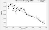
Fig. 7 depicts the scattered graph of a set of longitudes and latitudes of an MS at regular intervals of time. Best-fitted line was produced using excel and statistical analysis was effected by model linear regression. Dark circles represent longitudes and latitudes of the MS which moved through several BSs. Using curve fitting and interpolation, the best-fit line was generated. The perpendicular distance from the fitted line to each BS was then calculated and a threshold value for the distance was set. The next location of the MS can then be determined provided two conditions are fulfilled. a) Perpendicular distances from the BSs should be less than or equal to the threshold value b) Coordinates of selected BSs should be less than the coordinates of MS.
Plotted Graph of Movement Path of a MS
The plotted graph of a scattered data is illustrated in Fig. 7. Simulated data using NS2 were taken for determining the distance. Nine real data set of latitudes and longitudes of an MS were entered in the excel sheet and plotted as the movement path of MS. Latitudes and longitudes of five BSs were also utilized. The small black circles represent the location coordinates of the MS and black pyramids depicted the location coordinates of BSs. Best fitted line was produced using linear regression and the shortest distance of BS from that perpendicular line was delineated. The rounded pyramid indicated in the figure above, is the next predicted location of the MS.
Fig 8 shows the movement path of an MS simulated by the network simulator NS2. The six base stations BS1, BS2, BS3, BS4,BS5 and one mobile station MS are also represented in it. The mobile node starts from its initial position and moves randomly. Using NS2, the movement path can be traced.
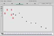
NS2 Simulation of Mobile Node Movement
Simulation of movements of the MS is traced by the simulator NS2 and the simulation screen depicts the movement path of the MS and six BSs. Table 1 represents the coordinates of the MS which were traced by the simulation tool NS2.
6.1. Inferring Congestion from Historical Data
Apart from the proposed location prediction technique, there is a scope for inferring the congestion at each BS from the historical data and make it useful for deciding which BS should be selected next. Since the system have large volume of location data of users it is possible to apply data analytics and mining techniques to find or infer the congested BSs. The data which we keep at the server are LA-ID, BS-ID, BS-Latitude, BS-Longitude, MS-ID, MS-Latitude, MS-Longitude, DATE-Of-Registration, and TIME-Of-Registration. To find the congestion happens on BS regularly, data which collected over 40 weeks were taken. These large amounts of historical data are processed and analysed to find all congested and non-congested BSs located in the current LA.
The shortest distance BS is checked across list of BSs generated by big data analytics. If that BS is found in the congested list, the second shortest distance BS is considered and so on. If any selected BS with distance lower than the threshold value, is existing at the opposite direction, can be eliminated from the list because MS is already located on that BS before the current location.
6.2. Algorithm of Hybrid Prediction
In this paper, a hybrid prediction method is used for predicting the next location of MS. The following algorithm describes the steps to find the next location of MS.
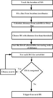
Algorithm of Hybrid Prediction
7. Conclusion
This paper studies many issues and corresponding solutions in location prediction in cellular networks done in several research papers. To overcome overall problems mentioned in those papers, this paper proposes a new hybrid prediction model which optimises the handoff delay and predict the next location of MS. Here, two innovative devices GPS integrated SIM and prediction server PS are introduced. The hybrid model describes two innovative ideas to predict the next location of MS through which handoff delay can be optimised.
References
Cite this article
TY  - JOUR
AU  - M R Regitha
AU  - Varghese Paul
AU  - Shailesh Sivan
AU  - Nijo Antony
PY  - 2018
DA  - 2018/04/30
TI  - Handoff Delay Optimization Using Hybrid Prediction Model
JO  - International Journal of Networked and Distributed Computing
SP  - 99
EP  - 107
VL  - 6
IS  - 2
SN  - 2211-7946
UR  - https://doi.org/10.2991/ijndc.2018.6.2.5
DO  - 10.2991/ijndc.2018.6.2.5
ID  - Regitha2018
ER  -