
Internet of Things in the 5G Mobile Communication System: The Optimal Number of Channels in Channel Hopping*
- DOI
- 10.2991/ijndc.2018.6.2.6How to use a DOI?
- Keywords
- IoT (Internet of Things); Channel Outage; Service Outage; QoS (Quality of Service); ONC (Optimal Number of Channels)
- Abstract
One of the typical goals of the 5G mobile communication system1 is to establish an Internet of Things (IoT)2 environment in which all objects are connected to the network to generate and share information through not only mobile terminals but also mobile communication infrastructure. 5G must support Machine-Type Communication (MTC)3 in IoT, and it must effectively support many devices distributed at high density. The IoT environment for MTC support has low transmission power and a narrowband channel environment and interference environment so that many devices can connect with minimum energy. In this environment, data transmission performance is negatively affected by retransmission, deep fading, and interference. One way of solving this problem is to propose various kinds of channel-hopping methods in which a frequency is periodically changed every time a packet is transmitted. However, current channel-hopping techniques do not indicate the proper number of channels to be used. In this paper, we propose the Optimal Number of Channels (ONC) in channel hopping algorithm, a reference method that can provide the optimal channel number to improve channel performance in 5G massive IoT environments. We show that using a hopping method that minimizes service inefficiency reduces the number of channels and improves the Quality of Service (QoS) of the channel.
- Copyright
- Copyright © 2018, the Authors. Published by Atlantis Press.
- Open Access
- This is an open access article under the CC BY-NC license (http://creativecommons.org/licences/by-nc/4.0/).
1. Introduction
To support massive Internet of Things (IoT), one of the goals of 5G, the communication channel of the Machine-Type Communication (MTC) device that performs narrowband transmission deeply fades and interferes with the transmission performance. To solve this problem, channel hopping is used to change the frequency in a fixed order at a predetermined time, thus increasing the diversity of channel as well as the transmission probability of massive devices4. Figure 1 shows how 5G works in a communication environment supporting a number of devices operating in the narrowband.
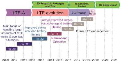
3GPP future timeline5
Channel outages happen when the Quality of Service (QoS) is not fulfilled because channel capacity drops below the required level over a time period because of fading and interference. The hopping method involves regularly changing channels to prevent channel hopping6. In the channel-hopping method, if the node is aware of the condition of the channel, the pattern changes.
If it has no information on the channel's condition, all of the channels change each hour according to the standard channel-hopping method. If it can receive feedback on the condition of the channel, using the centralized control method, the channels in good condition are chosen for the pattern, and there is an adaptive channel-hopping pattern where channels change between the chosen channels on a regular basis7–8.
2. Related Work
2.1. Trends in 5G IoT Standards
5G mobile communication systems require mobile communication technology with a maximum download speed of 20Gbps and a minimum download speed of 100Mbps. In addition, they make it possible to provide Internet service to 1 million devices within a radius of 1–2 km/s and freely communicate on high-speed trains traveling up to 500 km/h.9
In the ITU-R (ITU radio communication sector), users experience data rate, peak data rate, mobility, latency, connection density, energy efficiency, spectrum efficiency (frequency efficiency), and traffic volume density (capacity per area). One of the typical goals of the 5G mobile communication system is to establish an IoT environment in which all objects are connected to the network to generate and share information through not only mobile terminals but also mobile communication infrastructure.
Figure 2 illustrates three typical usage scenarios for the 5G mobile communication system: enhanced mobile broadband, massive IoT connection, low latency, and ultra-high reliability.2–4
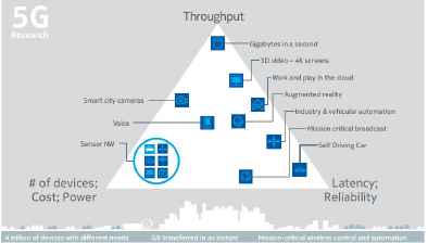
Diversity of services, use cases, and requirements10
To construct IoT, Massive IoT, a technology that effectively connects many devices distributed at a high density, devices require communication in MTC. These MTC devices have little mobility compared to HTC and have very short data transmission (periodic or intermittent).11–12
As shown in Figure 3, 5G will require a large amount of data to be communicated in 2030. Therefore, it is necessary to develop a large number of communication systems supporting LTE-A.13
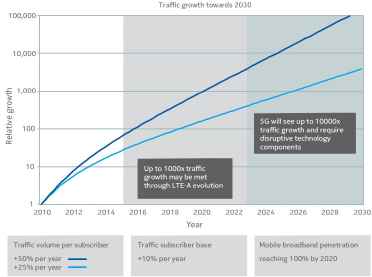
Predicted traffic volume 2017–203010
MTC devices can be located in places where it is difficult for humans to measure them and can be in environments that are difficult for signals to reach. Due to the low cost transmission requirements, low transmission power, and use of a narrowband frequency band, the channel’s performance can be lowered. To prevent this, a channel-hopping method is used in which the frequency is changed in a predetermined order at set times.
2.2. NB-IoT(Narrowband IoT)
Narrowband IoT (NB-IoT) is a 5G cellular narrowband wireless transmission technology for realizing a Low- Power Wide-Area (LPWA) network14, and it has NB- IoT standardization to support Massive IoT. It is expected that this technology will be able to accommodate massive communication devices that improve the coverage and perform small data transmission with low delay sensitivity.15
The performance requirements and targets for this are shown in Table 1.
| Performance | Objectives |
|---|---|
| Coverage enhancement | MCL 164dB |
| Reduced complexity | Ultra-low-cost module (approximately $1) |
| Power efficiency | 10-year battery life |
| Latency | 10 seconds for MAR exception reports |
| Capacity | 52,574 devices per cell |
| Coexistence | GSM (standalone) LTE (guard-band, in-band) |
Requirements of NB-IoT16
NB-IoT is mainly aimed at supporting a variety of services, such as smart metering, smart homes, and alarm services in the licensed band. Most NB-IoT devices do not require management, such as battery replacement once installed, and they transmit small data with low sensitivity. The base station can accommodate about 50,000 massive IoT devices per cell. Thus, frequency hopping is used to increase the probability of successful data transmission for devices using narrowband.
2.3. Frequency Hopping
Frequency hopping is a transmission technology used in wireless sensor networks and a technique to generate spread spectrum by hopping the carrier frequency.17 Frequency hopping communication schemes aimed at avoiding multiuser interference have been used for various devices. Such a frequency-hopping wireless communication system uses random codes in real time from the transmitter carrier frequency and pseudo-random hopping and transmitter to the receiver of the random hopping sequence. Therefore, the initial motivation needs to be match to find the exact frequency hopping. A hopping signal transmitted according to a sequence capable of receiving the synchronization structure is needed.
Synchronous frequency hopping is obtained in a very short period of time, and synchronization performance in a real system is difficult to measure. The frequency hopping periodically transmits while changing the frequency, and the hopping occurs in the frequency band. The channel used as a hopped channel is called instantaneous bandwidth, while the hopping spectrum is called hopping bandwidth.
Figure 4 depicts frequency hopping, hopping within the physical layer that increases safety by averaging all possible risk factors by preventing multiple frequencies in the packet from falling into deep fading.
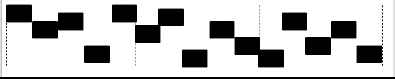
Frequency Hopping
2.4. Channel Hopping
In the current IEEE, 802.15.4e has as standard Time Division Multiple Access (TDMA) mode channel hopping. The typical multi-access technology, TDMA technology, as well as the wired environment, IEEE 802.15.3 WPAN, cellular systems, mobile internet, and mobile wireless environments are widely used medium-access technologies. For TDMA devices that use the same frequency at different times to communicate with each other, the time is divided into time slots that are assigned to the devices.
Even if channel hopping temporarily falls into deep fading, it quickly escapes fading, and when resent to increase the probability of success, as shown in Figure 5, it is the method of hopping within data link levels that changes the carrier frequency regularly within the packet.19
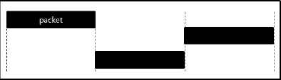
Channel Hopping
However, in this type of channel hopping when the condition of the channel is unknown, changing the channel according to the preset pattern presents a problem, in that it does not consider improving performance for communication.
2.5. Adaptive Channel Hopping
In adaptive channel hopping, the system periodically changes its main operation to avoid interference with other devices. The method avoids considering the channels that are in bad condition to improve the stability and performance of the network. The two metrics used to find out a channel’s condition, Packet Delivery Ratio (PDR) and Packet Loss Ratio (PLR), are collected over a set time period. Channels having higher PDR or PLR are categorized as “Lossy” and, therefore, are blacklisted. The blacklist is constantly changing depending on the changing channel conditions. The blacklist is in the form of a 16-bit mask, and each bit is consistent with the 16 channels. Based on this, blacklisted channels are excluded from the order of channel hopping.20 When using this hopping method, there must be a mechanism to select “good” and “bad” channels, and this method of adaptive hopping can be done by functionalizing one of the duplex channels as the feedback channel. The received information on the channel numbers that are in use is kept. In a duplex communication method, as shown in Figure 6, there is a sender A and a receiver B to inform on the uplink and downlink from the sender to receiver and select the frequency channel as the next hop to use the feedback from uplink.17
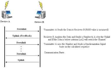
Communication scheme17
As a different adaptive channel-hopping method, the Received Signal Strength Indicator (RSSI) is collected, and only the channels that are over the standard are used. 21
Using adaptive channel hopping has the following advantages:
- •
Active avoidance of narrowband interference and frequency deep fading
- •
Avoids complicated and crowded frequencies in hopping sequence
- •
High BER (Bit Error Rate) performance
- •
Saves transmission power
- •
Working with adaptive channel further improves system performance
However, while these diverse types of adaptive channel hopping choose good channels depending on their communication status and can improve their performance depending on how much time has passed, the channel status can change into a state where communication is not possible.
2.6. Adaptive Frequency Hopping
Adaptive Frequency Hopping (AFH)24 is a technique designed to solve interference problems in different wireless technologies that share the 2.4 GHz band. This technique that uses frequencies that are available in the spectrum band. It is implemented as a way to avoid interference.
The AFH divides the 2.4GHz to 2.485GHz frequency band into 79 channels each having a width of 1 MHz, and uses an interval in which interference does not occur, thereby enabling more efficient transmission in the frequency band.
The frequency of the AFH is scaled randomly so that the sum of the “bad frequency” sets collected by all devices is represented, and the hopping sequence is changed by including the new frequency as much as the new hopping sequence except for the bad frequency set.
The existing channel hopping includes the “bad frequency” in the hopping sequence because it does hopping to a predetermined sequence without the state of the frequency.
However, if there is a WLAN DSSS(Direct Sequence Spread Spectrum), AFH eliminates the bad frequency by modifying the Bluetooth frequency hopping sequence, which can solve the packet loss problem, TCP delay and low channel efficiency, enabling more effective data transmission.
2.7. Hybrid Channel Hopping
The hybrid channel-hopping method mixes the standard channel-hopping method and adaptive channel-hopping method depending on the situation. For all of the 16 channels to communicate, when there are no communication problems for all 16 channels, the general hopping method is used. However, if communication failure occurs, the coordinator collects the status information of the channels and uses only the channel to be used for hopping. Because the coordinator wastes energy and storage space on gathering channel information for adaptive channel hopping, this method is more wasteful than the standard channel-hopping method. With the hybrid method, it is difficult to change all the channels, making it impractical to use.
2.8. Multiuser Diversity
If a base station has data to send to multiple users and the wireless channel from the base station to each user undergoes independent fading, multiuser diversity will show a good downlink channel status at a certain time, while others will not. In this case, the base station can maximize the throughput by preferentially serving users who show a good channel state. Considering fairness, the order of services among users should be determined and defined as opportunistic scheduling.
2.9. Multipath Fading
The radio signals originating from the transmitter each arrive at the receiver antenna with different phases through different paths. The strength of the combined signal may be smaller than the average depending on the phase of the signals passing through the different paths. It may also be bigger. We propose a method to solve this problem using the hopping method in the narrowband.
3. Optimal Number of Channels in a Channel – hopping Environment
In this section, we propose a method of finding the optimal number of channels to reduce the chances of a service outage.
3.1. Channel Outage
A channel outage leads to unsatisfactory communication service quality due to channel capacity reduction caused by fading and interference during a measured time. To conduct channel hopping, it needs to take place in channels that have a lower value than the channel outage by recognizing the condition of the channels to be selected.
This paper attempts to assess the processes of predicting the condition of the channels to be chosen and determining channels available for use in channel hopping by conducting a comparison between the conditions of the channels and channel outage.22 To analyze the outage probability, we need to two parameters: diversity order and coding gain.
Expressing this is the log out verse signal-to-noise ratio (SNR). This approach is expressed as a probability considering diversity characteristics that can operate in various kinds of fading channels.
3.1.1. Methods for inferring the condition of channels to be chosen
To select channels available for use in channel hopping, it is necessary to recognize the condition of the channels to be chosen. This can be conducted by making inferences with the measured conditions of past channels. The method of inferring the condition of channels to be chosen can be expressed in Eq.(1) .23
Assuming that the number of channels that can be used in channel hopping is K, if the measured past value of the k (1≤k≤K) channel is defined as hk, old, the condition of the chosen channel can be defined as in Eq.(1) when data transfer occurs.
ρk is the correlation coefficient between new channels and measured channels. hrandom refers to the complex Gaussian random variable. If hrandom is 0, it indicates that the previous channel had no relation in the past, but if it is 1, it indicates that it is in the same condition as a new channel. By using this, changes in the condition of selected channels can be inferred.
3.1.2. Comparing current channel conditions and channel outage for channel selection
The method of obtaining the channel capacity of the current kth channel expressed as Ck can be defined as shown below in Eq.(2).
Here,
The coordinator sequentially arranges each of the 16 channels in order of channel inefficiency from small to large according to the channel state. This is expressed as
Count (b, M) can be expressed as N-M, where the channel state is 1, that is, the sum of impossible channels is denoted by M, and the channel state is 0, that is, the usable channel minus the sum of the channels that are impossible in the entire channel N. Count (b, M) denotes the number of channels in all situations. In this case, the channel state of the channels is a probability of being disabled and a probability of being available. Eq.(4) explains the probability that M channels are disabled when N channels are used.
This can be expressed as follows.
3.2. Service Outage
The coordinator selects channels that were lower than the channel outage threshold in adaptive channel hopping. However, when channel outage uses the single lowest channel or all of the channels are used in channel outage lower than the threshold, after a set period of time the condition of the channels will deteriorate and in the case a single channel cannot be used
Therefore, the service outage is not determined by the number of channels but combination of the channel states. If unnecessary channels are use sending data, eventually it will be created where either all of the data cannot be sent or many channels will be used creating channel waste and optimal service for communication can't be provided. We propose a method of the optimal number of channels and the channel hopping pattern for minimizing service outage in this section.
3.2.1 Channel selection for service outage
For channel hopping, if many channels are selected and used, because the channel outage for each of the channels is different, combining them can create a number of different probabilities in value.
At this point, the combination of channels needs to be lower than the service outage for communication to be possible, and this is expressed as follows. The service outage (N) can be expressed as SON, and when the total number of channels is K and 1 ≤ N ≤ K channels are used, the PLR is higher than the PLR.22
M(1≤M≤N) denotes channels that cannot communicate in N number of channels, and MaxPLR is the maximum allowable PLR. If the average value of the combined channel outage of the channels is greater than the MaxPLR, communication is impossible, and it is expressed as a service outage.
Eq. (5) obtains average service outage through combination of channels that cannot use channels using Eq. (4). In other words, the M channel probability, which is a channel combination of channel outage in N total channels, is expressed as a service outage This can be expressed as follows in Eq. (5).
3.2.2 The optimal number of channels to minimize service outage
The combination of channels for hopping is the goal to create optimal conditions for communication through minimizing service outages, because the channel state is improved as the service outages are reduced. The optimal channel number can be expressed by Eq. (6) by selecting a channel that minimizes service outages.
In Eq. (6), NOPT denotes the optimal number of channels that can minimize the average value SO(N) of non-communicable channels when the average combined channel outage of the N channels is large.
In the conventional method, channel hopping is used by selecting only a channel having a high PDR. However, our proposed scheme finds the optimal number of channels for hopping and eliminates unnecessary channel usage. Therefore, it creates the best hopping pattern by minimizing service inefficiency.
4. Experiments
In the conventional method, only channels with a low PLR were chosen and used in channel hopping, but the proposed method will calculate the optimal number of channels for hopping. Thus, the method eliminates the use of unnecessary channels, and by reducing service outages as much as possible, it creates the best hopping pattern.
Table 2 shows the simulation environment variables for finding the optimal number of channels used for channel hopping.
| Attribute | Value |
|---|---|
| Number of channels | 16 |
| MaxPLR | 0.25/0.28 |
| Channel state | failure 1, success 0 |
| Channel outage | 0.1 |
Simulation variable values
The number of channels used is 16, the channel outage is 0.1, and the condition of the channels is only expressed as 0 or 1.
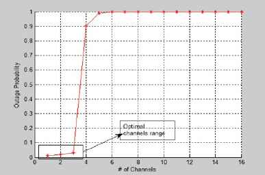
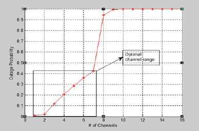
It is assumed that if the conditions are better than the channel outage, it results in success, and if they are not as good, it results in failure. The MaxPLRs of 0.25 and 0.28 were tested. Figures 7 and 8 show that with a MaxPLR of 0.25 and 0.28, service outages can be minimized.
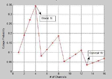
The rate service outage according to the number of channels (MaxPLR:0.25)
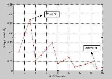
The rate service outage according to the number of channels (MaxPLR:0.25)
Through Table 3 shows both the optimal number of channels and the number of channels when service outage is at its worst.
| MaxPLR | Channel outage P(F1:F16) | Channel combination | Service outage |
|---|---|---|---|
| 0.25 Figure 7 |
0.1 | {F1,F2,F3,F4} | 0.33 |
| {F1,F2,F3,F4,F5,F6.............F13} | 0.03 | ||
| 0.28 Figure 8 |
0.1 | {F1,F2,F3} | 0.27 |
| {F1,F2,F3,F4,F5,F6.............F15} | 0.02 | ||
Optimal number of channels
In the environment variables shown in Table 4, the number of channels being used is 16 and the MaxPLR is 0.1. Channel outage was divided into two groups: one where channel conditions were good and one where they were bad. Tests were run on these two groups. Figures 9 and 10 show the groups divided into good and bad and show that they are affected by service outage and different numbers of channels.
Rate of service outages according to number of channels (channel outage 0.01/0.9)
Rate of service outages according to number of channels (channel outage 0.01/0.1/0.9)
| Attribute | Value |
|---|---|
| Number of channels | 16 |
| MaxPLR | 0.1 |
| Channel state | failure 1, success 0 |
| Channel outage P(F1:F3), P(F4:F16), P(F1:F2),P(F3:F7), P(F4:F16) | 0.01/0.9/0.01/0.1/0.9 |
Variable values
Table 5 shows the results that can be divided into the group that can minimize service outages and the group that can maximize service outage.
| MaxPLR | Channel outage | Channel combination | Service outage |
|---|---|---|---|
| 0.1 | 0.01 | {F1} | 0.02 |
| Figure 9 | 0.9 | More than 6 channels | 1 |
| 0.1 | 0.01 | {F1} | 0.02 |
| Figure 10 | 0.9 | More than 9 channels | 1 |
The combination of channels according to the service outage
If in the existing channel-hopping method, the standard is set and only channels in good condition are chosen for hopping, but the method proposed in this paper is not about simply choosing good channels but about presenting a standard channel pattern for hopping that minimizes service outages. While creating the channel pattern using the method proposed in this paper, we were able to show through the results the number of channels and channel combination that result in minimal outages.
5. Conclusions
In this paper, to support massive IoT among the representative targets of 5G, in a network system using adaptive channel hopping, which is used to improve the channel state of devices communicating in the narrowband, the number of channels that minimize service outages according to the channel state was obtained.
Using adaptive channel hopping, we verified that we can obtain channels to minimize service outages depending on the condition of the channels in a network system. In the existing method of creating hopping patterns, a clear standard method for choosing channels is not presented, and it is limited, in that it simply chooses good channels.25
This paper applied an optimal number of channels (ONC) algorithm of hopping to the optimal channel pattern by determining the number of channels that minimizes the service inefficiency in a way that defines the precise criteria of channel selection to determine the pattern of channel hopping. As a result, we proposed a method to improve channel QoS and reduce unnecessary channel waste by using a channel-selection method based on an accurate channel-reference method.
Acknowledgements
This work was supported by the National Research Foundation of Korea (NRF) grant funded by the Korean government (MSIP) (No. 2016R1A2B1008953).
Footnotes
Internet of Things in the 5G Mobile Communication System: The Optimal Number of Channels in Channel Hopping
Computer Engineering, Information and Communication Engineering, Dongguk University Seoul
Seoul, 04620, Republic of Korea
References
Cite this article
TY  - JOUR
AU  - Gayoung Kim
AU  - Minjoong Rim
PY  - 2018
DA  - 2018/04/30
TI  - Internet of Things in the 5G Mobile Communication System: The Optimal Number of Channels in Channel Hopping*
JO  - International Journal of Networked and Distributed Computing
SP  - 108
EP  - 117
VL  - 6
IS  - 2
SN  - 2211-7946
UR  - https://doi.org/10.2991/ijndc.2018.6.2.6
DO  - 10.2991/ijndc.2018.6.2.6
ID  - Kim2018
ER  -