
Optimizing the Motion for Robotic Snap Assembly Using FEM
- DOI
- 10.2991/jrnal.2018.5.2.7How to use a DOI?
- Keywords
- Robotic Assembly; Snap joints; Strain Energy
- Abstract
In this paper, we aim to provide a better assembly method for a snap joints assembly task. We create a 3D cellphone model and use ADAMS simulation environment to analyze the relative motion between screen and backer part. We focus on two points in this research. 1) Two kinds of relative motion between the screen and backer parts, i.e., the rotation-based and the translation-based methods, are compared, and 2) difference between assembly and disassembly is analyzed. By using the maximum elastic energy in an assembly process, we show that 1) the rotation-based assembly motion has better robustness than the translation-based assembly motion in cellphone assembly tasks when we set the same initial position error. 2) The rotation-based assembly method is more effective when we disassembly the cellphone screen part.
- Copyright
- Copyright © 2018, the Authors. Published by Atlantis Press.
- Open Access
- This is an open access article under the CC BY-NC license (http://creativecommons.org/licences/by-nc/4.0/).
1. Introduction
Snap joints connection is one of the typical examples of plastic parts assemblage. As the widely application and mass-production of plastic parts, snap joints assembly is becoming more and more popular in assemble method of Industrial products. In snap joint assembly, the connection between two parts is built by elastic deformation of snap joints. [1] Fig.1 shows an example of the snap assembly task. Because of the elastic deformation of the snap joints, it becomes relatively hard for an industry robot to finish snap joints assembly task [2–3]. As for the research on robotic snap joints assembly. Rojas et al. have proposed a force control method [4–6] and identification of assembly state for the snap assembly problem.
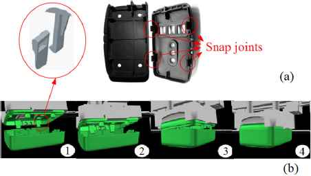
Snap assembly task
Rojas et al. focus on the identification of assembly state in 2012 and prove that the rotation-based assembly method is more robust against the error of part’s pose than the translation-based method in robotic snap assembly [7].
In 2016, we proposed the Extend Directional Blocking graph for snap assembly [7]. We also proposed the Maximum Elastic Energy (MEE) used for the Extended Directional Blocking graph to evaluate the easiness or difficulty of snap assembly where smaller MEE implies the easiness of snap joints assembly [8].We analyzed the motion of snap joints assembly based dynamic simulation by using FEM. We proposed a simulation based method to compute the MEE [9–10].
In this paper we aim to provide a better assembly method for a cellphone snap joints assembly task. We create a 3D model of a cellphone, and use ADAMS simulation environment to analyze the assembly process of the cellphone. Using the Maximum Elastic Energy (MEE) as an index for evaluating the quality of a snap joints assembly tasks, we compare two kinds of assembly methods, i.e., rotation-based and translation-based methods. We also compare the difference of MEE in assembly and disassembly when we choose different assembly method.
By using the maximum elastic energy in an assembly process, we show that 1) Rotation-based assembly motion has better robustness than the translation-based assembly motion in cellphone assembly tasks. When we set the same initial position error. 2) The rotation-based assembly method is more effective when we disassembly the cellphone screen part.
2. Approach and Definitions
We create a 3D model of a cellphone used in ADAMS physics simulation environment where the screen part contains four snap joints as shown in Fig. 2. We simulate the assembly process by using the redefined relative motion between two parts. Throughout a physics simulation of a snap joint assembly, we consider obtaining the function curve of strain energy. And select the MEE from the strain energy curve.
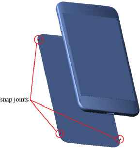
3D cellphone model.
We consider Ei(s) as the total elastic energy in the assembly process. Here, s is a scalar ranging from 0 to 1. It indicates the states of assembly. 0 is the starting state. 1 is the goal state. A value between them is an intermediate state. The maximum elastic energy (MEE) Ui is being defined for snap assembly/disassembly task of Part i. [8]
We use Adams physics simulation environment analyze the assembly process. We can get the strain energy-duration function curve in Adams. And select the MEE from the curve. By compare the MEE of different assembly methods, we can choose the better assembly method which the MEE is smaller.
3. Experiment and Analysis.
In this section, we set two kinds of relative motion for cellphone assembly task, the rotation based relative motion is shown in Fig. 3, and translation based relative motion is shown in Fig. 4. We compute and compare the MEE of rotation-based/translation-based relative motion. And the better assembly method is be defined as the one bring smaller MEE in assembly process.
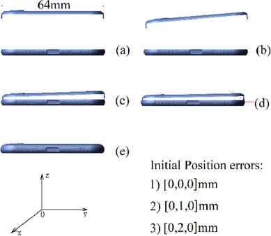
Rotation-based relative motion and Initial position errors.
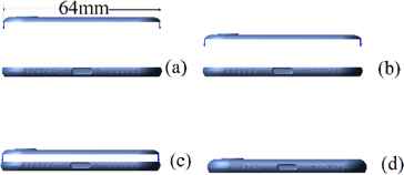
Translation-based relative motion.
3.1 Initial Position Errors.
In robotic assembly tasks. Influence of initial positon errors always been used as a criterion of robustness. In our experiment, we set the initial position errors of screen part to 0mm, 1mm, 2mm (Fig. 3) to compare the rotation- based and translation-based assembly motion.
Fig. 5 and Fig 6 shows the simulation results when we set the initial position errors to 0mm. The result shown the strain energy of translation based-motion (1.19J) is bigger than the rotation-based motion (0.94J).
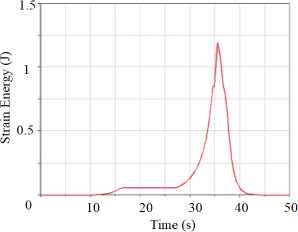
Strain energy of 0mm position error in translation-based assembly
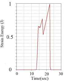
Strain energy of 0mm position error in rotation-based assembly
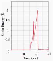
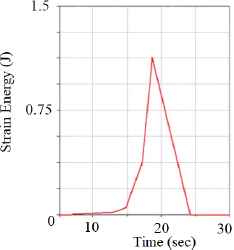
Fig. 7 and Fig. 8 shows the simulation result when we set the initial position errors to 1mm. The result shown the strain energy of translation based-motion (2.17J) is bigger than the rotation-based motion (1.12J). Fig. 9 and Fig. 10 shows the simulation result when we set the initial position errors to 1mm. The result shown the strain energy of translation based-motion (3.51J) is bigger than the rotation-based motion (1.13J).
Strain energy of 1mm position error in translation-based assembly
Strain energy of 1mm position error in rotation-based assembly
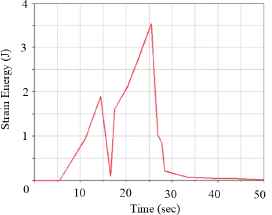
Strain energy of 2mm position error in translation-based assembly
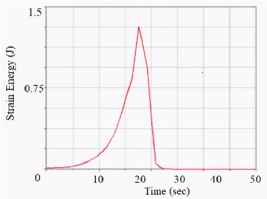
Strain energy of 2mm position error in rotation-based assembly
The simulation result shown a conclusion: when we set the same initial position errors, the MEE in rotation-based assembly process is smaller than translation-based assembly process. And proved rotation-based assembly method has better robustness than translation-based assembly method.
3.2 difference of assembly and disassembly.
As the second point, we analyze the difference of assembly and disassembly in two kind of assembly methods. The MEE is different in assembly and disassembly when we use translation-based assembly method. Fig. 11 shows the MEE in assembly/disassembly process based on translation-based relative motion. The MEE in assembly process is 1.19J, it is smaller than the MEE in disassembly process (1.52J). Nevertheless, Fig. 12 shows the MEE in assembly/disassembly process when we use rotation-based assembly method, the MEE is almost same in assembly and disassembly process (0.94J).
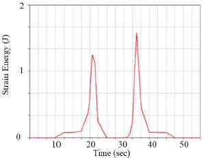
Strain energy of assembly/disassembly process in translation-based assembly
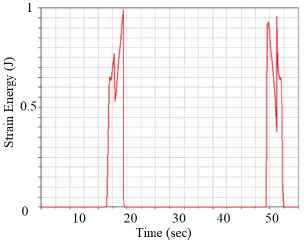
Strain energy of assembly/disassembly process in rotation-based assembly
The simulation result shown that the rotation based assembly method is more effective when we disassembly the cellphone screen part.
4. Conclusions.
This paper analyzes the 3D cellphone snap joints assembly task. We compare two kinds of assembly method from the following points. First is the initial position errors of screen part. Second is difference between assembly and disassembly.
We use ADAMS to simulate the snap joints assembly motion and get the strain energy curve to compute the MEE. Take the cellphone screen snap assembly task for example.
We proposed method evaluates the MEE of rotation based and translation based assembly, selects a better assembly method for a cellphone snap joints assembly task. We also compare the difference of MEE in assembly and disassembly when we choose different assembly method.
Based on the simulation result. We can draw the following conclusions: the rotation-based assembly method has better robustness than translation-based assembly method when we set same initial positon error. The rotation-based assembly method is more effective when we disassembly the cellphone screen part.
References
Cite this article
TY  - JOUR
AU  - Peihao Shi
AU  - Kensuke Harada
AU  - Weiwei Wan
AU  - Ixchel G. Ramirez
AU  - Juan Rojas
AU  - Hiromu Onda
PY  - 2018
DA  - 2018/09/30
TI  - Optimizing the Motion for Robotic Snap Assembly Using FEM
JO  - Journal of Robotics, Networking and Artificial Life
SP  - 105
EP  - 109
VL  - 5
IS  - 2
SN  - 2352-6386
UR  - https://doi.org/10.2991/jrnal.2018.5.2.7
DO  - 10.2991/jrnal.2018.5.2.7
ID  - Shi2018
ER  -