
Self-repairing Adaptive PID Control for Plants with Sensor Failures
- DOI
- 10.2991/jrnal.2018.5.2.8How to use a DOI?
- Keywords
- PID control; Adaptive control; Fault-tolerant control; Sensor failure
- Abstract
This paper presents a new design method for a self-repairing adaptive PID control system. The control system has the adaptive adjusting mechanisms for the PID gains, and also can detect the sensor failure by self-test using the integrator in the PID controller. Hence, for plants with unknown parameters, self-repairing control can be successfully attained. Furthermore, in this paper, the control performances are theoretically analyzed.
- Copyright
- Copyright © 2018, the Authors. Published by Atlantis Press.
- Open Access
- This is an open access article under the CC BY-NC license (http://creativecommons.org/licences/by-nc/4.0/).
1. Introduction
Against sensor failure, several types of self-repairing control systems (SRCS) have been developed in the previous works. The SRCS can detect failure by self-testing using the internal signals, and automatically replace the failed sensor with the healthy backup to maintain its stability. They belong to active fault-tolerant control (AFTC) based on dynamic redundancy1. The main difference (feature point) from the conventional AFTC is that the fault detector is quite simple, and its structure does not depend on the mathematical model of the plant.2,3,4 For example, the integrator in the PID controller can be utilized as fault detector for the SRCS5.
However, in most existing SRCSs, roughly estimated parameters of plants are required to construct the controller. This paper presents a new design method for a self-repairing adaptive PID control system. The control system has the adaptive adjusting mechanisms for the PID gains, and also can detect the sensor failure by self-test using the integrator in the PID controller. Thus, no a priori information about the plant is needed to attain the SRC. The proposed SRCS is expected to be widely utilized as fault-tolerant PID control.
Furthermore, in this paper, the control stability, failure detection and sensor-recovery are theoretically analyzed. In addition, the numerical simulation is explored to confirm the effectiveness of the proposed adaptive SRCS.
Throughout this paper, with x ∈ ℝ, we define the “sgn” function by
2. Problem Statement
Consider the following linear time invariant system:
For measurement of the output y, the two sensors are exploited; one is the primary sensor #1 and the other is the backup sensor #2 for occasion of failure. Then, the measured feedback signal can be represented as
The problem to be considered here, is to construct the active fault-tolerant PID control system for plant with unknown parameters and sensor failures (3), that can automatically replace the failed sensor with the backup to maintain the control stability.
3. Basin Design of the Control System
First of all, the adaptive PID controller is designed by
In the above adaptive controller, the PID gains, kP: ℝ+ → ℝ+ , kI: ℝ+ → ℝ and kD: ℝ+ → ℝ are adaptively tuned as follows.
Here, we shall analyze the control stability on the time period [0, tF) where the sensor is healthy, i.e., ys = y. Now, define the augmented signal ɛ: ℝ+ → ℝ by
Consider the positive definite function S: ℝ+ → ℝ+ :
Taking the time derivative of S, gives
The block diagram of the proposed control system is illustrated in Fig. 1.
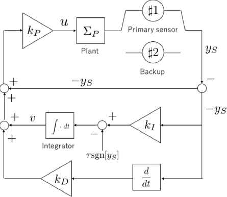
Block diagram of the proposed adaptive PID control system with self-repairing function.
4. Failure Detection & Repairing
This section shows the concrete detection method utilizing the integrator (5).
From the above discussion, on the time period [0, tF), there exists Γ ∈ ℝ+ such that
5. Numerical Simulation
To confirm the effectiveness of the proposed method, the numerical simulation is explored.
Consider the following unstable plant:
For the above plant, we construct the adaptive PID controller based on (4) and (5). By trial and error, the design parameters are selected as follows.
The simulation results are shown in Figs. 2 and 3.
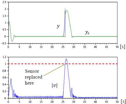
Simulation results: the measured output, the actual output and the absolute value of the the integrator output.
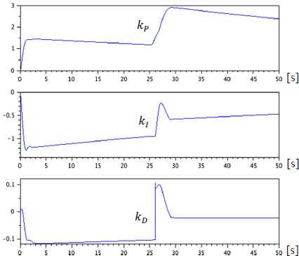
Simulation results: the three adaptive PID gains.
In Fig. 2, the measured output ys, the actual output y(top) and the absolute value of v(bottom) are shown.
Also, in Fig. 3, the three adaptive gains, kp (top), kI (middle) and kD (bottom) are shown.
From these results, it is clear that the failure (17) can be found and the failed sensor is replaced at tD ≅ 26[s]. Furthermore, the control system can be well stabilized, and the actual output converges to a very small ball before and after the failure.
6. Conclusions
In this paper, a new adaptive PID control system has been developed that has self-repairing function against sensor failures, and the concrete failure detection is shown by using the integrator in the adaptive PID controller. The applications to MIMO case, nonlinear systems and so on are still left in the future works.
Acknowledgment
This work is supported by JSPS KAKENHI Grant Number JP16K06429.
References
Cite this article
TY  - JOUR
AU  - Masanori Takahashi
PY  - 2018
DA  - 2018/09/30
TI  - Self-repairing Adaptive PID Control for Plants with Sensor Failures
JO  - Journal of Robotics, Networking and Artificial Life
SP  - 110
EP  - 113
VL  - 5
IS  - 2
SN  - 2352-6386
UR  - https://doi.org/10.2991/jrnal.2018.5.2.8
DO  - 10.2991/jrnal.2018.5.2.8
ID  - Takahashi2018
ER  -