
Finding appropriate parameter voltages for driving a low-power analog silicon neuron circuit
- DOI
- 10.2991/jrnal.2018.5.1.16How to use a DOI?
- Keywords
- neuromorphic hardware; neuromorphic chip; silicon neurons; analog VLSI
- Abstract
This research focuses on a silicon neuron circuit designed utilizing a qualitative neuronal modeling approach. In this circuit, temperature, fabrication mismatch, and secondary effects of transistors cause the difference between the intended characteristics and those in the implemented circuits. Therefore, we have to tune the bias voltages for each neuron instance to realize the desired dynamical behavior after circuit implementation. We constructed an algorithm to automatically find appropriate values for the bias voltages.
- Copyright
- Copyright © 2018, the Authors. Published by Atlantis Press.
- Open Access
- This is an open access article under the CC BY-NC license (http://creativecommons.org/licences/by-nc/4.0/).
1. Introduction
Silicon neuron is electronic circuit that mimics electrophysiological behavior of neurons. It is supposed to be used as the basic elements of silicon neural networks, whose aim is to simulate the behavior of the nervous system in real-time or faster. They can be used not only as the high-speed brain simulators for neuroscientific researches but also as a basic technology for the next generation low-power intelligent computing systems. In addition, they can be used to construct bio-silico hybrid systems in connection with neurons, which can be an ideal technology for neuroprosthetic devices.
In this research, we focus on an analog silicon neuron circuit designed by using the techniques of qualitative neuronal modeling whose power consumption is as low as about 3 nW.1 This circuit is composed of metal-oxide-semiconductor field-effect transistors (MOSFETs) in their subthreshold region for low-power consumption. By utilizing the qualitative modeling techniques, the model of this circuit was designed so that it can reproduce the dynamical structures in the excitable nerve membrane. The parameter tuning procedure is supported by the feedback amplifiers integrated in the silicon neuron circuit.
The characteristics of this circuit are influenced by temperature, transistors’ fabrication mismatch, and their secondary effects (short channel effect, etc). They make the expected circuit characteristics in designing stage and actual behavior of the individual circuit inconsistent. Therefore, it is required to adjust bias voltages of transistors in silicon neuron circuit to get the desired dynamical behavior.
The procedure to do it by hand has been established3, but it is not realistic to execute the procedure for each silicon neuron circuit when we build the large-scale silicon neuronal networks comparable to the human brain which contains about 100 billion neurons.
To solve this issue, a system to fit characteristics of silicon neuron automatically is essential. In this work, the same metaheuristic algorithm used in the previous similar works2, 3, 4, the Differential Evolution (DE) method5, is used to find proper bias voltages. The DE method performed better in terms of convergence speed and simulation time, compared to other popular metaheuristic algorithms, such as Genetic Algorithm and Simulated Annealing.3 All the results in this work was obtained by circuit simulation using ngspice.
Our silicon neuron model is explained in the next section and our parameter fitting algorithm is in section 3. The results and discussion are in section 4 and 5, respectively.
2. A low-power analog silicon neuron model
Our silicon neuron circuit is composed of two blocks, the v- and n-blocks (Figure 1). Each block’s dynamics is represented as below. Block diagram of our qualitative-modeling-based low power silicon neuron circuit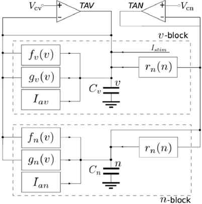
For each function, fx(v) (x = v, n) is an ideal I-V characteristics of a differential pair circuit, gx(v) and rn(n) are ideal I-V characteristics of a cascoded transistor circuit with source degeneration with a detached bulk voltage. Both of them are in sigmoidal shape and the latter has shallower gradient than the former. They are combined to construct the mathematical structures in the neurons. Iax and Istim are constant current and input stimulus, respectively. They are generated by transconductance amplifiers.
There are nine bias voltages to tune this circuit, one of which is related to the time constant of n and the others affect the shape of the sigmoidal curves.
Our circuit can reproduce Class1 and 2 neurons in the Hodgkin’s classification6, by reconstructing specific dynamical structures for each class. In this work, we concentrated on the Class1 neuron mode of our circuit.
To estimate the dynamical structures in our circuit, the transconducance amplifiers (TAV and TAN in Figure 1) are used to draw the nullcline of each variable. The nullclines are drawn by measuring the current Iv, the output current of TAV, and In, the output current of rn(n), while sweeping VCV in DC analysis. Their equations are represented as below.
3. Automatic parameter voltages fitting algorithm
Figure 2 illustrates the block diagram of our automatic parameter fitting system. Here, we use circuit simulation instead of actual circuit measurement because this work focuses on the efficient verification of our fitting algorithm in this system. It finds the appropriate parameter values by optimizing the difference between the reference data and the simulation result.
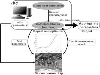
Automatic bias voltages tuning system for silicon neuron
This optimization is done by using the DE method which searches for the best-fitted parameter vector by repeating the mutation, crossover, and selection of parameter vectors for a number of generations. The automatic parameter fitting algorithm we suggest is composed of the 2 steps explained below.
3.1. Step1: Fitting nullclines
At first, we fit the shape of the v- and n-nullclines to a given reference nullclines. Figure 3 shows the nullclines in the Class1 neuron mode without stimulus. The two nullclines intersect each other at three points, “S”, “T”, and “U”. They represent a stable node, a saddle point, and an unstable node, respectively. Point “S” corresponds to the resting state and “T” is responsible for the threshold phenomena of neuronal spike generation.
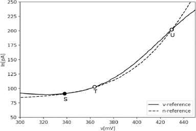
Nullclines in the Class1 neuron mode
The fitness function for the DE method is calculated by summing the difference between the nullcines obtained in the simulation and the reference nullclines. The fitness function is written as follows:
Initial vectors are generated in the range between − 100mV and +100mV compared to the values used for generating the reference data. The DE method’s optimization step was repeated for 400 generations and 40 vectors were contained in each generation.
3.2. Step2: Fitting neuron characteristics
The nullcline fitting procedure in Step1 was not sufficient to produce the desired behavior similar to the reference model, because our circuit’s dynamical properties are sensitive to the shape of the nullclines and rn_Vm cannot be fitted in Step1. In this step, we fit the dynamical behavior in response to stimulus using the DE method. Threshold current, spike width in response to pulse stimulus, and spike frequency in response to sustained stimulus are used for fitness function.
The definition of the threshold current is the minimum amplitude of the pulse stimulus that makes the membrane voltage exceed 400mV. The spike width is defined as time width when the membrane voltage at the middle of the spike amplitude.
Our silicon neuron circuit is equipped with transconductance amplifiers for generating current stimulus. Pulse stimulus with 500 μs time width was generated by applying a pulse voltage to the transconductance amplifier. We applied pulse stimulus with a variety of amplitude by increasing the pulse voltage by 7mV step for 20 pulses. The threshold current and the spike width were measured with the firstly observed spike in this sequence.
For the spike frequency, two amplitudes of sustained stimulus, 10pA and 15pA, were applied for 300ms using the transconductance amplifier.
All of the 9 parameters are tuned in this step. The initial parameter value was distributed in the range within the value obtained by Step1 ± 2 mV except for rn_Vm. For rn_Vm, an initial value was found by sweeping until spikes are generated in response to both pulse and sustained stimulus with the other parameters’ value obtained by Step1. The range for this sweeping was between the reference model’s parameter value (435 mV) −6mV to +12mV.
In this step, the fitness function is calculated as follows:
a is obtained by each transient simulation result and b is obtained by the reference model. Elements of weight vector, W, are calculated by dividing Ithrref by elements of b, respectively.
In this step, the DE method’s step was repeated for 200 generations and 45 vectors were contained in each generation.
4. Results
Table1 shows the characteristic of our silicon neuron circuit with the parameters obtained by our fitting algorithm. For all the criteria, the error is less than 4%.
Figure 4 shows the reference transient data and simulation results of the fitted circuit. The amplitude of spikes seems to be well fitted.
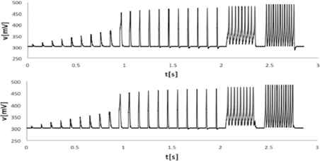
Transient data of the reference (top) and the simulation results of the tuned circuit (bottom)
The reference data was generated by using ngspice simulation. Thus the ideal fitting result is identical to the parameter set used for the reference data generation, with which the error is zero. But as shown in Table 1, our algorithm could not find the original parameter set but found a local optimum point.
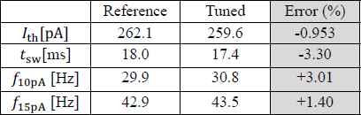
Comparison of silicon neuron characteristics
5. Discussion
In this research, we proposed an algorithm to find proper parameter values to obtain the desired dynamical properties for individual silicon neuron circuit instance. This algorithm will be crucial for operation of large-scale silicon neuron networks. The error for the criteria in the fitting procedure was less than 4%. From the viewpoint of engineering application, defining the maximum acceptable error is a difficult problem, because it depends on specific applications but they are not established yet. From the viewpoint of neuromimetics, this error is acceptable when our algorithm is used to tune a number of silicon neuron instances to Class 1, because there is a wide distribution (far larger than 4%) of dynamical properties in the same class of neuronal cells.
We will also try to apply this algorithm in fitting Class2 neuron. In addition, our algorithm will be improved to be applicable to the three variable ultralow-power silicon neuron circuit.7 This circuit can realize a wide variety of neuronal classes such as the regular spiking, the square-wave bursting, and the elliptic bursting.
In the future, we will apply this algorithm to a real circuit.
Acknowledgement
This study was partially supported by JST PRESTO and CREST and JSPS-MAEDI SAKURA Program.
References
Cite this article
TY  - JOUR
AU  - Atsuya Tange
AU  - Takashi Kohno
PY  - 2018
DA  - 2018/06/30
TI  - Finding appropriate parameter voltages for driving a low-power analog silicon neuron circuit
JO  - Journal of Robotics, Networking and Artificial Life
SP  - 71
EP  - 74
VL  - 5
IS  - 1
SN  - 2352-6386
UR  - https://doi.org/10.2991/jrnal.2018.5.1.16
DO  - 10.2991/jrnal.2018.5.1.16
ID  - Tange2018
ER  -