
Parameter Optimization with Input/Output Data via DE for Adaptive Control System with Neural Network
- DOI
- 10.2991/jrnal.2018.5.1.5How to use a DOI?
- Keywords
- Adaptive Control; ASPR; PFC; Neural network; Differential evolution
- Abstract
In this paper, adaptive control system with neural network (NN) will be designed. At the beginning, parallel feedforward compensator (PFC) will be designed by using one-shot experimental data of controlled system via differential evolution (DE). From the obtained PFC and the ideal almost strictly positive real (ASPR) model, nominal model of controlled system can be obtained. Then, parameters of adjust law for NN will be optimized by using obtained nominal model via DE.
- Copyright
- Copyright © 2018, the Authors. Published by Atlantis Press.
- Open Access
- This is an open access article under the CC BY-NC license (http://creativecommons.org/licences/by-nc/4.0/).
1. Introduction
In spite of their simple structure, Almost strictly positive real (ASPR) based adaptive control systems have high robustness with respect to disturbances and uncertainties1,2. However, the ASPR conditions which controlled system has to satisfy are very severe conditions for actual systems. To overcome this problem, introduction of parallel feedforward compensator (PFC) has been proposed3. Several design methods of PFC which are based on mathematical model of controlled system such as relative degree have been proposed4. However, to obtain the mathematical model, iterative of identification experiments have to be done and it cost time and money. Therefore, a design method which is using system’s input/output data has been proposed5,6. For ASPR system, an adaptive control system with feedforward input generated by neural network (NN) has been proposed7. This input is applied to avoid tracking error caused by PFC. In theory, PFC and NN parameters can be any value if the conditions are satisfied. However, those parameters will directly affect control performance. Therefore, it has to be appropriate value in actual control systems. Since there are no decision method for those parameters, designer has been decided it by trial and error of numerical simulations. Therefore, it is quite difficult to decide appropriate value.
In this paper, the parameter optimization method of PFC and NN by using input/output data via differential evolution (DE) will be proposed. DE is one of the evolutionary computation methods and it has a good convergence and uniqueness of solution8.
2. Adaptive Control System with Adaptive NN Feedforward Input
Consider the controlled system is described in equation state model as follows.
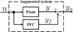
Block diagram of augmented system.
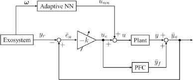
Block diagram of adaptive control system with NN feedforward input.
Here, the problems are how to design the PFC and how to decide the parameters of adjusting laws.
3. Design of PFC by Input/Output Data
Define the ideal output of the ideal augmented system with the input data as follows.
4. Differential Evolution
In this section, the basic algorithm of DE which is applied in this study will be shown.
(i) Creation of initial population
Randomly create an initial N sets of population as follows.
The superscript means a generation number of the vector, and D is the order of decision variables.
(ii) Extraction of base vector
Extract the best vector from nth generation vector
(iii) Mutation
Generate a mutated vector from randomly chosen two vectors
Here, F is a scaling factor for scaling the difference vector.
(iv) Crossover
Generate a trial vector from the target vector and the mutated vector as follows.
Here, C is a crossover rate, randi,j is a random uniform numbers in the range [0, 1] and jr is a randomly chosen integer number in the range [1, D].
(v) Selection
Select the next generation as follows.
5. Control System Design via Differential Evolution
Here, concrete designing method of control system via DE will be shown.
(i) PFC design
- (a)
Obtain the input/output data set of controlled system.
- (b)
Creation of initial population
Randomly create an initial N sets of population as follows
- (c)
- (d)
Mutation
Generate a mutated vector from randomly chosen two vectors as Eq. (22).
- (e)
Crossover
Generate a trial vector from the target vector and the mutated vector as Eq. (23).
- (f)
Selection
Select the next generation as Eq. (24).
(ii) Adaptive controller design
- (a)
Obtain an approximation model of controlled system
From ASPR model
- (b)
Creation of initial population
Randomly create an initial N sets of population as follows
- (c)
Extraction of base vector
Extract the best vector from nth generation vector as Eq. (21) which minimizing the evaluation function as follows.
- (d)
Mutation
Generate a mutated vector from randomly chosen two vectors as Eq. (22).
- (e)
Crossover
Generate a trial vector from the target vector and the mutated vector as Eq. (23).
- (f)
Selection
Select the next generation as Eq. (24).
6. Numerical Simulation
Assume that input/output data shown in Fig. 3 are obtained. From these data, by setting the parameters F = 0.8 and C=0.9 with ASPR model
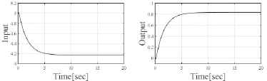
Control input/output data.
The initial value of design parameters were
Then the optimized parameters were
Fig. 4 and Fig. 5 show the control result by initial adaptive controller parameters and optimized parameters respectively. It can be seen that the control performance became better after optimizing the parameters.
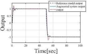
Control result by initial parameters.
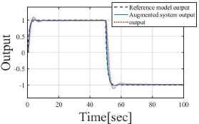
Control result by optimized parameters.
7. Conclusions
In this paper, the parameter optimization method which using input/output data via DE was proposed. The numerical simulation shows the usefulness of the method.
References
Cite this article
TY  - JOUR
AU  - Taro Takagi
AU  - Ikuro Mizumoto
PY  - 2018
DA  - 2018/06/30
TI  - Parameter Optimization with Input/Output Data via DE for Adaptive Control System with Neural Network
JO  - Journal of Robotics, Networking and Artificial Life
SP  - 19
EP  - 22
VL  - 5
IS  - 1
SN  - 2352-6386
UR  - https://doi.org/10.2991/jrnal.2018.5.1.5
DO  - 10.2991/jrnal.2018.5.1.5
ID  - Takagi2018
ER  -