
Design of an Intelligent Vehicle Environment Monitoring System based on WiFi
- DOI
- 10.2991/jrnal.k.211108.004How to use a DOI?
- Keywords
- Automobile internal environment; temperature and humidity sensor; smoke sensor; STM32F103; WiFi
- Abstract
The internal environment of the vehicle affects the driver’s state to a certain extent, so it is necessary to design an intelligent vehicle internal environment monitoring system. In this paper, a STM32F103 single-chip microcomputer is used as the core controller, which integrates multiple sensors including temperature sensors, humidity sensors and so on to collect various environmental information in the vehicle, and transmits the data to the monitoring platform through WiFi wireless communication. When the detected vehicle interior environment data exceeds the preset safety value, the monitoring system will automatically generate an alarm to remind the user to carry out relevant operations. Lower cost, more convenient use and higher precision would make the system have certain commercial value and market prospect.
- Copyright
- © 2021 The Author. Published by Atlantis Press International B.V.
- Open Access
- This is an open access article distributed under the CC BY-NC 4.0 license (http://creativecommons.org/licenses/by-nc/4.0/).
1. INTRODUCTION
At present, the car is an indispensable means of transportation in daily life. The internal environment of the car affects the physical condition of the driver and passengers to a certain extent. Therefore, it is necessary to design an intelligent vehicle internal environment monitoring system. The multi-function internal environment monitoring system can collect the temperature, humidity, Carbon Monoxide (CO) concentration and other internal environment information in the car in real time, and display them on the Liquid Crystal Display (LCD) screen. When the detected data exceeds the preset threshold, the monitoring system will generate an alarm to remind the user to carry out corresponding operation. The system can also transmit various data information to the monitoring platform through WiFi wireless communication, and users can view the historical data information on the monitoring platform. The vehicle interior environment monitoring system can effectively monitor and alarm the vehicle interior environment information in real time. The system is convenient to use and has a certain market value.
2. MAIN CONTROL CHIP AND PERIPHERAL CIRCUIT
The overall hardware structure of the system is composed of main control chip and peripheral modules, as shown in Figure 1. The multifunctional internal environment monitoring system selects STM32F103VET6 single-chip computer as the core controller of the hardware control system. The processor of STM32F103VET6 is ARM Cortex-M3 high performance kernel, with a maximum operating frequency of 72 MHz, Flash memory of 512 KB, SRAM of 64 KB, and encapsulated in LQFP64 [1]. Its peripheral configuration is strong and supports many communication interfaces including Serial Peripheral Interface (SPI), I2C interface, Universal Serial Bus (USB) interface, Universal Synchronous Asynchronous Receiver Transmitter (USART) interface, Analog to Digital Converter (ADC), timer and other peripherals [2]. With 80 IO ports, it is easy to connect peripheral modules for function expansion. The powerful function ensures that the chip can fully meet the hardware functional requirements of the whole system.
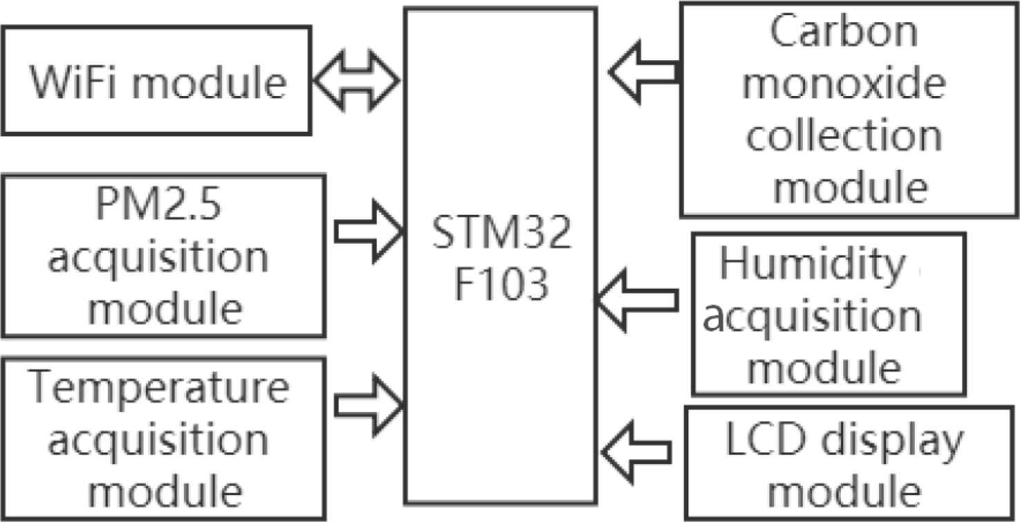
Overall architecture of hardware system.
2.1. AD Converter Circuit
STM32F103 master control has three ADCs, and each ADC has 16 conversion channels. The conversion accuracy is 12 bits and the resolution is 1/4096. The ADC conversion circuit is shown in Figure 2. The dynamic contacts of the patch sliding rheostat of the AD conversion circuit in the monitoring and control system are connected to the ADC channel pins of the Microprogrammed Control Unit (MCU) chip. When the user rotates the sliding rheostat adjustment knob, the magnitude of the dynamic contact voltage in the AD conversion circuit part of the system will change accordingly. The range of voltage change is 0–3.3 V, which is also the default ADC voltage collection range of the hardware end circuit board of the system.
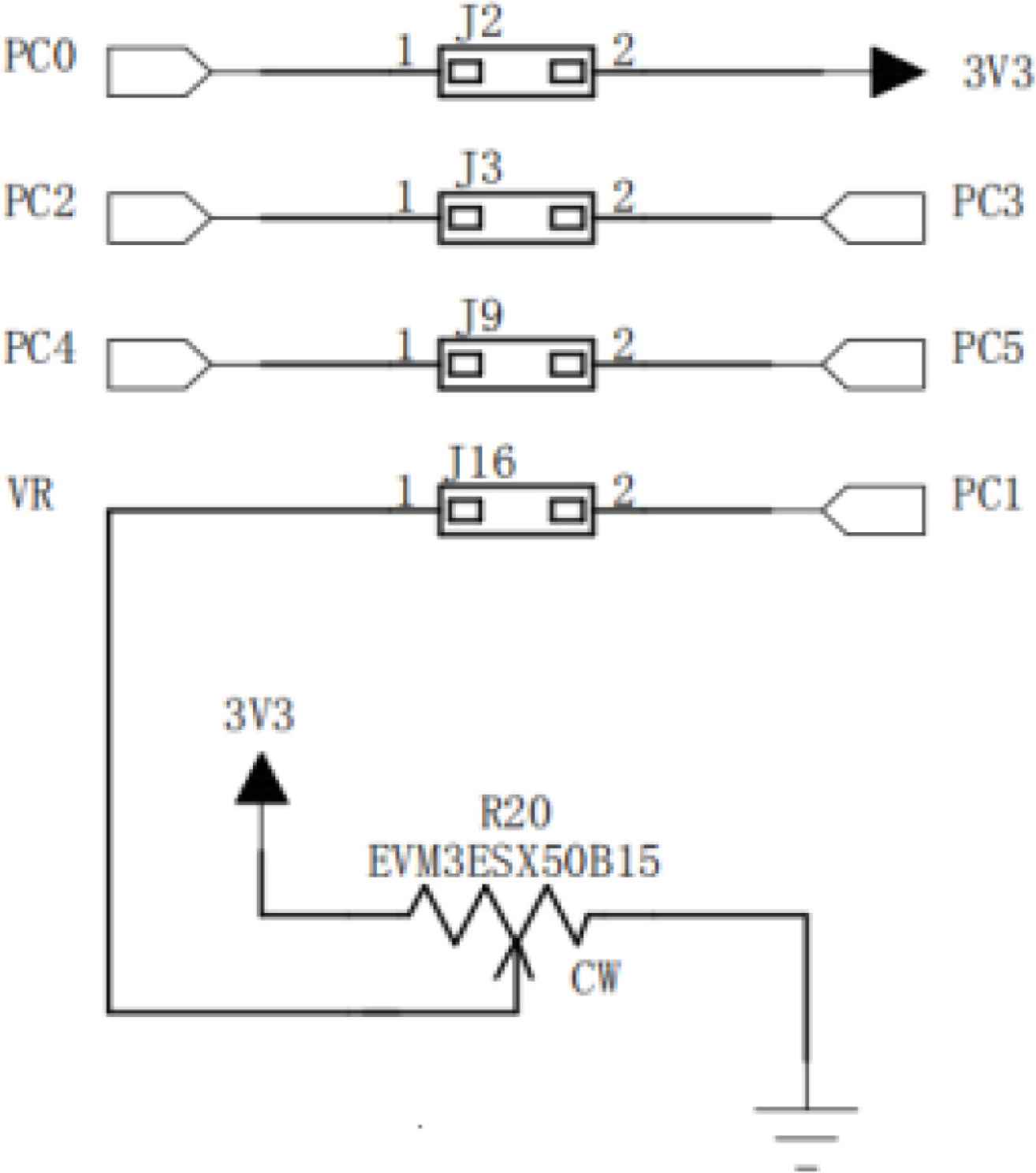
ADC converter circuit.
2.2. JTAG Interface Circuit Design
Joint Test Action Group (JTAG) is an international standard test protocol. It mainly tests the internal MCU chips but also simulates and debugs the hardware control part of the monitoring and control system. The basic principle of JTAG is to define a tap inside the device and test the internal nodes through a special JTAG test tool. Most complex devices support the JTAG protocol, such as arm, Digital Signal Processor (DSP), Field Programmable Gate Array (FPGA) and so on. As shown in Figure 3, there are four main lines in the JTAG interface part: Test Mode Selection (TMS), Test Clock (TCK), Test Data Input (TDI), Test Data Output (TDO), which are mode selection, clock, data input and data output lines respectively. In the design of the monitoring and control system, the JTAG interface circuit uses 20-pin interface wiring connection.
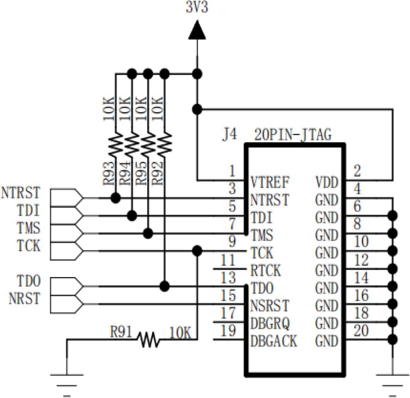
JTAG download circuit.
3. PERIPHERAL MODULE OF THE HARDWARE SYSTEM
The peripheral modules of the hardware system mainly include sensor nodes and communication modules. The following mainly introduces the selection and design of the temperature and humidity sensor, smoke sensor, interactive display screen and WiFi module.
3.1. Temperature and Humidity Sensor
DHT11 digital temperature and humidity sensor is a temperature and humidity composite sensor with calibrated digital signal output. By using special digital module collection and temperature and humidity sensor technology, the environmental monitoring and control system has strong reliability and stability for temperature and humidity detection of the environment. The DHT11 module has low cost and strong anti-jamming capability, and it can measure the relative temperature and humidity of the automotive interior environment quickly. DHT11 sensors are calibrated in an extremely accurate humidity calibration room. The calibration coefficients are stored in One Time Programable (OTP) memory in the form of program. These calibration coefficients are called during the processing of detection signals inside the sensor. As shown in Figure 4, the DHT11 module contains a capacitive humidity sensor to measure ambient humidity and an Negative Temperature Coefficient (NTC) temperature sensor to measure ambient temperature. Besides, a small, high-performance 8 bit MCU is connected to the module.
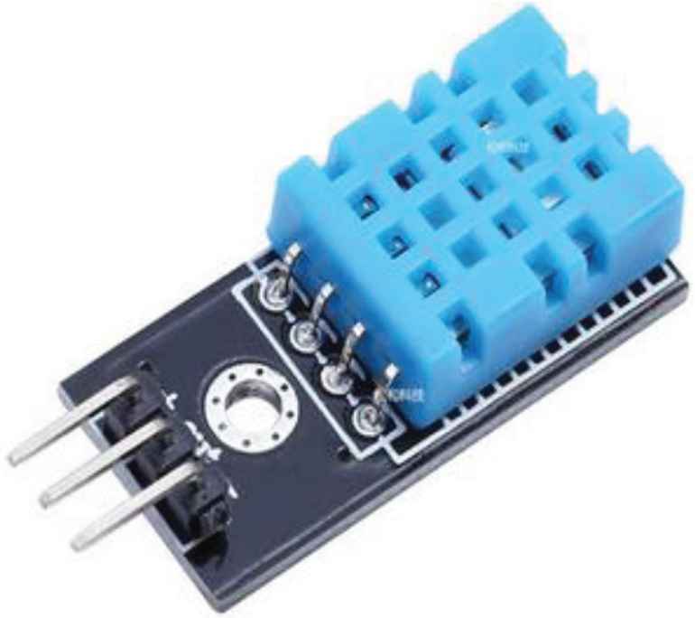
DHT11 sensor.
3.2. MQ-2 Sensor
The physical picture of the MQ-2 is shown in Figure 5. MQ Series sensors are low-cost sensors, which are widely used in gas leakage monitoring devices in homes or factories. The MQ-2 gas sensor used in the environmental monitoring and control system can detect the presence of liquefied gas, butane, methane or alcohol in the environment which are potentially dangerous to human health. The sensitive material used in MQ Series sensors is metal oxide semiconductor with high activity. After the sensor is heated, the conductivity is different in different gas concentrations. The current smoke concentration value is output from the sensor signal by the conditioning circuit and sent to the MCU for processing. The alarm concentration of this sensor is 0 when it is not set, and the alarm concentration threshold can be set by the user with an upper limit of 100%. The MQ-2 sensor has a wide detection radius, maintains high sensitivity and fast response in a variety of complex environments and excellent stability in harsh environments.
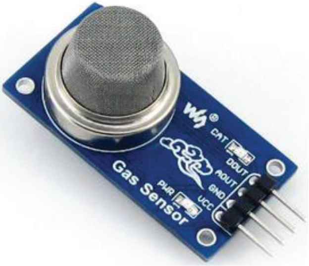
MQ-2 sensor.
3.3. ESP8266 Module
ESP8266 WIFI wireless communication module is selected as the data transmission bridge between smart hardware and server in this system, as shown in Figure 6. The ESP8266 module integrates a low power ESP8266 chip developed by LEXIN Information Technology Company (Shanghai, China). The chip is highly integrated with a built-in TCP/IP protocol stack and TR switches, amplifiers, regulators, power management components, etc. Its on-chip storage and processing power is strong, and it requires very few peripheral circuits, so it is easy to embed and develop [3].
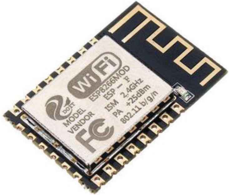
ESP8266 module.
The ESP8266 module is powered by a 3.3-V voltage and operates in three modes: Soft AP mode, Station mode and SoftAP+ Station coexistence mode. In the Soft AP mode, the module is equivalent to a wireless access point providing wireless access services, and other terminal devices can establish a local area network for data transmission through esp8266 connection; in the Station mode, this module is equivalent to a wireless terminal, which can connect to the Internet through a router and transmit data to the server; in the SoftAP+ Station coexistence mode, ESP8266 module can establish LAN communication with other terminal devices as a wireless access point, and can also connect services for Internet communication [4].
The ESP8266 module usually uses the Transfer Control Protocol (TCP) and User Datagram Protocol (UDP) for data transmission. UDP is a connectionless and unreliable protocol. It is impossible to determine whether the data is complete during transmission. TCP protocol is a reliable link-oriented protocol. It needs to wait for the confirmation of the receiver before establishing a connection. It can ensure the integrity of data. The ESP8266 module in this system uses the TCP protocol to set the WiFi application mode of ESP8266 as STA mode through AT instruction, and chooses TCP connection to realize the function of establishing data connection with the server.
3.4. User Interactive Display Module
The display is composed of the LCD display panel, capacitive touch panel and Printed Circuit Board (PCB) substrate. The touch panel is equipped with a touch control chip, which is specially designed to handle the touch signals generated by the user when he touches the display, and then transmits the information through the outgoing signal lines. Because the MCU of the system cannot control the LCD panel directly, a LCD controller is needed to deal with the process of displaying. MCU only needs to give the data to the controller to display.
4. SOFTWARE DEVELOPMENT ENVIRONMENT
This system chooses to develop the STM32F103VET6 controller in Keil5 development environment, and chooses C language as the development language. Keil5 is an integrated development environment with powerful compilation and simulation debugging capabilities.
STM32 is developed in two ways: register development and library development. This system is developed in the way of Library development, calling function interface directly to configure registers, which is fast and readable. Use STMISP downloader to program the STM32 core controller. The TCP serial debugging assistant is used to test the system function.
The core controller of STM32 needs to collect data information of each sensor module, and control each peripheral module to realize the sub-functions of the system through the internal logical analysis and processing.
5. CONCLUSION
The intelligent vehicle environment monitoring system based on WiFi designed in this paper can realize the pre-designed functions. LCD can display the data collected by each sensor to the user in real time. When the data exceeds the set threshold, the system will automatically send an alarm. Through the serial port debugging assistant, the WiFi communication function is normal, and the hardware device can connect through the WiFi module and send data to the cloud server.
CONFLICTS OF INTEREST
The author declares no conflicts of interest.
AUTHOR INTRODUCTION
Mr. Yuqi Yan
 He majored in Mechanical Engineering in Wuhan University of Technology, China, majoring in mechanical design and manufacturing, automatic programming and other related courses. During his study, he learned relevant knowledge of STM32 microcontroller and conducted relevant experiments, involving motor control, sensor data reading and so on.
REFERENCES
Cite this article
TY  - JOUR
AU  - Yuqi Yan
PY  - 2021
DA  - 2021/12/27
TI  - Design of an Intelligent Vehicle Environment Monitoring System based on WiFi
JO  - Journal of Robotics, Networking and Artificial Life
SP  - 249
EP  - 252
VL  - 8
IS  - 4
SN  - 2352-6386
UR  - https://doi.org/10.2991/jrnal.k.211108.004
DO  - 10.2991/jrnal.k.211108.004
ID  - Yan2021
ER  -