
Effects of Variable Arm Length on UAV Control Systems
- DOI
- 10.2991/jrnal.k.200528.004How to use a DOI?
- Keywords
- UAV; quadrotor; moment of bending; arm length
- Abstract
Quadrotor is a type of unmanned aerial vehicle that has been widely used in many applications, such as, policing, surveillance, aerial photography and agriculture. Conventionally, the control of quadrotor flight direction is accomplished by varying speeds of rotors or manipulating torques. In this paper, a novel mechanism is proposed. The mechanism uses stepper rotors to control the arm length for changing flight directions, while maintaining rotors’ speed at constant. This can be achieved using a mathematical analysis of relation between quadrotor arm length and moment of bending of various position of rotor. Analysis and simulation results have shown the change in arm length required to produce moment of bending for hovering, roll and pitch motion. Experimental results have shown that the new mechanism is able to carry more payloads which the rotor speed can be utilized fully at 100% while the flight direction is been controlled by changing of the arm length compared to conventional flight control mechanisms.
- Copyright
- © 2020 The Authors. Published by Atlantis Press SARL.
- Open Access
- This is an open access article distributed under the CC BY-NC 4.0 license (http://creativecommons.org/licenses/by-nc/4.0/).
1. INTRODUCTION
UAV is a short name for “Unmanned Aerial Vehicle” defined as aircrafts without the onboard presence of pilots [1]. UAV is commonly used in military and police forces in situations where the risk in sending a human piloted air craft is unacceptable. In many developed countries, UAV is also used to perform tasks, for example intelligence, surveillance, and reconnaissance missions. Small UAVs can also be used for entertainment industry, such as, aerial filming, aerial photography and others. Most of the UAVs are made in quadrotor due to its easy to design, small rotors, and excellent manoeuvrability [2]. The study requires analyzing the relationship between UAV’s rotor support bar length and the UAV control systems. Quadrotor is a type of UAV that is lifted and propel by four rotors. The propellers are connected with two pairs of support bars. The flight direction of quadrotor can be controlled by increasing or decreasing the speed of rotors [3,4]. Predicting the motion of manipulators are based on an artificial neural network [5–10].
Larger rotor required quite high current, which are difficult to control using current or voltage regulating circuitry. Also, power usage of the UAV systems is a major problem to withstand the desired endurance of flight time. A study to manage the power usage is important and a study from fluid mechanic’s point of view is much needed. Besides that, flight movement of quadrotor limits the power of rotor. Quadrotor rotors cannot operate in 100% power because of another 30% of power is reserved to control for flight direction. Furthermore it is difficult to control the stability and precision of flight movement of quadrotor that powered by fuel or petrol [11,12].
Therefore, the theory is implied to control the quadrotor’s direction of flight by increasing or decreasing the length of the support bar. The length of support bar helps in balancing and stabilizing the UAV. The study focus on relation between support bar length and moment of bending of various position of rotor. Thus, this study shall be the basis to run the dynamic analysis at the UAV’s rotor support bar length control systems and also to enhance the UAV’s mathematical modelling by using (SOLIDWORKS® software, Dassault Systèmes), computer-aided design (CAD) and computer-aided engineering (CAE) systems [13].
2. QUADROTOR DYNAMIC MODEL
Quadrotor is an UAV that consist of four rotors located at the end of the cross configuration. Each of the rotor consists of propeller that generate thrust force for lifting the quadrotor [12]. The front and rear rotor rotate counter-clockwise, while the left and the right rotor rotate clockwise [14]. The rotations allow to nearly canceling the gyroscopic effects and aerodynamic torques in trimmed flight [15]. The quadrotor is able to move in yaw, roll, pitch and hover direction with the change of thrust outputs of each propeller. In Figure 1a, hover movement is obtained when the net thrust of all the rotors is equal to zero. In order to achieve zero net thrust for all rotors, the direction of rotation of rotor 1 and 3 must be in the opposite direction of rotor 2 and 4. Besides that, all the rotors are operated in equal speed. When the speed of rotor (1–4) are increased equally as shown in Figure 1, the quadrotor flies in vertical motion along z-axis according to the thrust output produce due to the propeller rotation. In Figure 1b, pitch movement is obtained when the torque of rotor 3 is increase/decrease and the torque of rotor 1 is decrease/increase and keeping constant torque of rotor 2 and 4. The quadrotor will pitch forward or backward. In Figure 1c, roll movement is obtained when the torque of rotor 4 is increase/decrease and the torque of rotor 2 is decrease/increase and keeping constant torque of rotor 1 and 3. The quadrotor will roll right or roll left. In Figure 1d, yaw movement is obtained when the torque of rotor 2 and 4 is increase while decrease the torque of the rotor 1 and 3 to move left and vice versa for the right direction. The quadrotor will rotate clockwise or counter-clockwise.
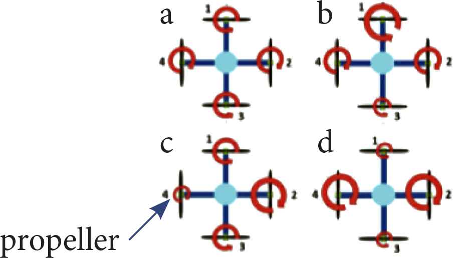
Movement of the quadrotor due to propeller rotation.
Quadrotor is non-linear system with six degree of freedom and contains only four rotors input [15]. Figure 2 represents the free body diagram and axes of the quadrotor. In Figure 2, l is the distance of each rotor toward the center of the pivot. ϕ, θ and ψ are representing the Euler angles about the body axes x, y, z. F1, F2, F3 and F4 are the thrust force produce by the propeller.
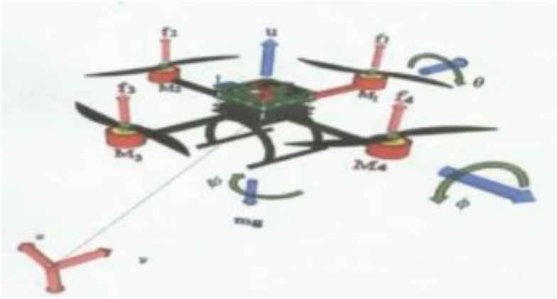
Free body diagram of the quadrotor [11].
The position and velocity vectors in Earth frame stated as
The pitch, roll and yaw angle in body frame are stated as
Then, R indicates the rotational matrix from body to earth frame as
In Equation (5), c indicates cos() and s indicates sin().
The thrust force and control torque act on the body and produced by the propeller rotation. The vector of thrust moves from body frame to earth frame. Applying the Newton–Euler method for rigid body as:
Thus, the input vectors are defined as:
3. VARYING ARM LENGTH
Figure 3a indicates the pitch movement that is produced by the decreasing the arm length l1 and increasing the arm length l3 and keeping both arm length l2 and l4 length unchanged. Figure 3b shows the pitch movement produced when the arm length l1 is increased and the arm length l3 is decreased and kept constant length in both arm length l2 and l4. Figure 3c illustrates the roll movement that is obtained when the arm length l2 is decreased and the arm length l4 is increased while keeping the length of both l1 and l3 fixed. Figure 3d shows the roll movement that is obtained when the arm length l2 is increased and the arm length l4 is increased while keeping the length of both l1 and l3 fixed. In Figure 3e, the yaw movement is accomplished by increasing the arm length l2, l4 and decreasing the arm length l1, l3. Thus, the quadrotor tilted in counter-clockwise direction. Figure 3f indicates the yaw movement in clockwise direction produced by decreasing the arm length l1, l3 and increasing the arm length l2, l4. Equation (10) that stated earlier explains the input torque produced by the increasing and decreasing the rotor speed. According to torque law:
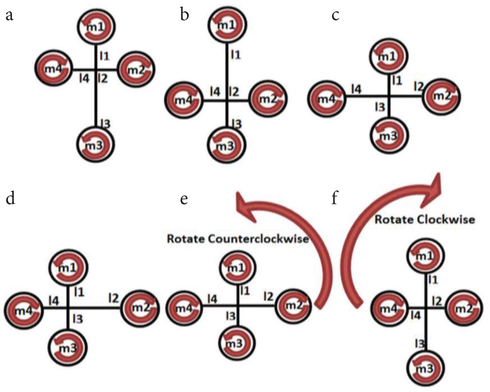
Pitch, roll, yaw moment respect to arm length.
The input torque is derived as:
Therefore, the pitch, yaw, roll movement of the quadrotor can be controlled by increasing or decreasing arm length to generate the certain input torque. The rotor speed is kept at constant where wi = w1 = w2 = w3 = w4.
4. MATHEMATICAL ANALYSIS OF QUADROTOR ARM LENGTH
The analysis is conducted by referring KDE data performance Table 1. KDEdirect.com provides data performance of specific rotor version for its suitable propeller size and voltage. Rotor version that suited well with 18.5″ diameter and 6.3 mm pitch propeller is KDE5215XF-435 (435 KV). The data consists of amperage, power input, thrust output, RPM and efficiency for different throttle range between 25% and 100%. The data is obtained from the experiments conducted by the KDE Company.
| Rotor version | Voltage [V] | Propeller size | Throttle range | Amperage | Power input | Thrust output | RPM | Efficiency | ||||
|---|---|---|---|---|---|---|---|---|---|---|---|---|
| [A] | [W] | [hp] | [g] | [N] | [lb] | [Rev/Min] | [g/W] | [lb/hp] | ||||
| (Lower is better) | (Higher is better) | (Higher is better) | (Higher is better) | (Higher is better) | ||||||||
| KDE5215XF- 435 (435 KV) KDEXF-UAS75HVC S.R.ENABLED | 14.8 V(4S) 16.8 V MAX | 18.5″ × 6.3 KDE-CF185-DP DUAL BLADE | 25.00% | 2.1 | 31 | 0.04 | 430 | 4.22 | 0.95 | 1980 | 13.87 | 22.8 |
| 37.50% | 4.6 | 68 | 0.09 | 860 | 8.43 | 1.9 | 2820 | 12.65 | 20.79 | |||
| 50.00% | 8.3 | 122 | 0.16 | 1390 | 13.63 | 3.06 | 3600 | 11.39 | 18.73 | |||
| 62.50% | 13.6 | 201 | 0.27 | 2010 | 19.71 | 4.43 | 4320 | 10 | 16.44 | |||
| 75.00% | 20.6 | 304 | 0.41 | 2710 | 26.58 | 5.97 | 4980 | 8.91 | 14.66 | |||
| 87.50% | 29.7 | 439 | 0.59 | 3510 | 34.42 | 7.74 | 5640 | 8 | 13.14 | |||
| 100.00% | 39.3 | 581 | 0.78 | 4420 | 43.35 | 9.74 | 6240 | 7.61 | 12.51 | |||
KDE data performance
5. DETERMINING MOMENT OF BENDING FOR EVERY ROTOR SPEED (RPM)
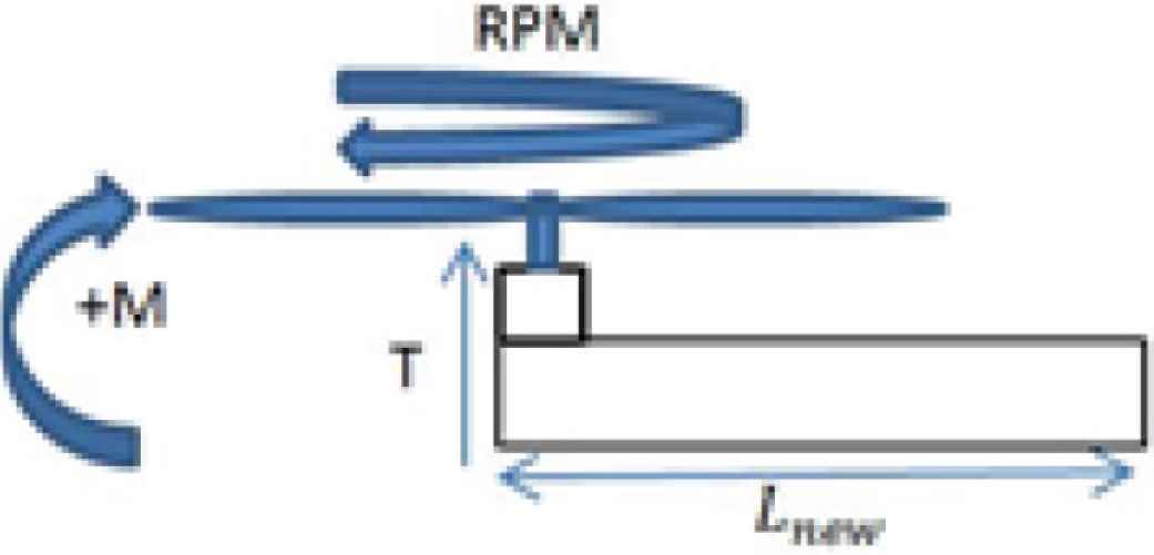
Figure 4 shows the free body diagram of the quadrotor. In order to produce hover movement, the equivalent net torque of the quadrotor is equal to zero and all rotor spinning in equal speeds. Moment of bending acting on quadrotor arm can be calculated using the formula as shown in Equation (14).
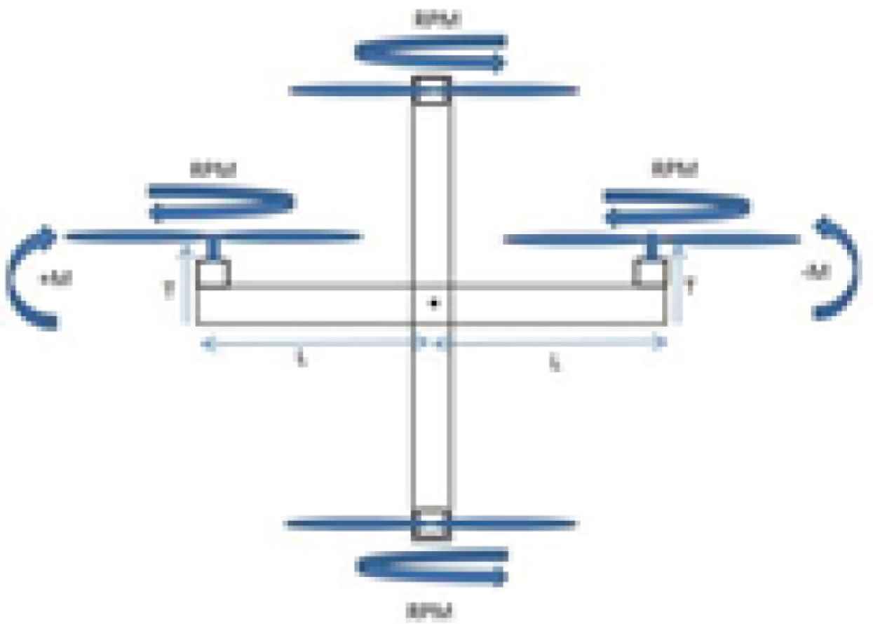
Free body diagram respect to moment thrust and length.
M is the moment of force, T is the force or thrust output produce by the propeller rotation and L is the quadrotor arm length, and I = 1, 2, 3, 4, 5, 6, 7. In the first step of the analysis, there are two variables, a fixed variable and a manipulated variable. The fixed variable is the length of the quadrotor arm, L. The manipulated variable is the thrust output produced from variation rotor speeds. The length of the quadrotor arm is 400 mm suitable for 18.5″ propeller. Quadrotor hover in vertical direction, when the all four-rotor spinning in equal speed, produces the same amount of thrust. Higher speed produces more thrust so that the quadrotor flies higher and vice versa for lower speed. Therefore, the moment of bending can be calculated for every speed of rotor provided from KDE data performance.
6. DETERMINING THE CHANGE IN QUADROTOR ARM LENGTH
Finding arm length needed to produce a required moment from previous data using thrust output produce from three rotor speeds of 3600, 4320 and 4980 RPM (Figure 5). The constant variable now is change to thrust output produced from a fixed rotor speed and the manipulated variable is the moment of bending, Mi. Their relationship is shown in Equation (15).
Free body diagram for one arm.
7. ASSEMBLY DESIGN OF THE QUADROTOR ARM
The design requires a stepper rotor, a fixed arm, a moving arm, 4 × 18.5″ propellers and a brushless DC rotor (Figure 6).
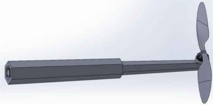
Assembly design of the quadrotor arm.
8. RESULTS
Figure 7 shows the relation of moment of bending against the thrust output. In the diagram, we can see that the moment of bending is increased directly that is proportional to the thrust output. Thrust output produced by the rotation of the propeller is also related to the speed of rotor Table 2. The increased in rotor speed results in higher thrust generated. The minimum value of moment of bending is 1.69 N.m acting on 0.4 m quadrotor arm length, with the thrust output of 4.22 N. The moment of bending increases until it reaches to the maximum value of 17.34 N.m with the thrust output of 43.35 N.
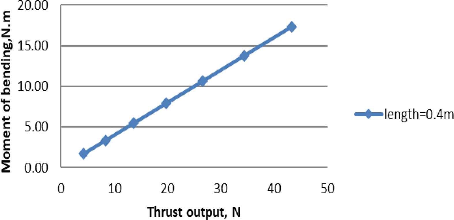
Graph moment of bending against thrust output.
| Rotor version | Propeller size | Throttle range | RPM [Rev/Min] (Higher is better) | Thrust output | Arm length (m) | Moment of bending (N.m) | ||
|---|---|---|---|---|---|---|---|---|
| [g] | [N] | [lb] | ||||||
| (Higher is better) | ||||||||
| 25.00% | 1980 | 430 | 4.22 | 0.95 | 0.4 | 1.69 | ||
| KDE5215XF-435 (435 KV) KDEXF-UAS75HVC | 37.50% | 2820 | 860 | 8.43 | 1.9 | 0.4 | 3.37 | |
| 18.5″× 6.3 | 50.00% | 3600 | 1390 | 13.63 | 3.06 | 0.4 | 5.54 | |
| KDE-CF185-DP | 62.50% | 4320 | 2010 | 19.71 | 4.43 | 0.4 | 7.88 | |
| DUAL-BLADE | 75.00% | 4980 | 2710 | 26.58 | 5.97 | 0.4 | 10.63 | |
| S.R.ENABLED | 87.50% | 5640 | 3510 | 34.42 | 7.74 | 0.4 | 13.77 | |
| 100.00% | 6240 | 4420 | 43.35 | 9.74 | 0.4 | 17.34 | ||
Data moment of bending due to various rotor speed
9. RESULT OF ARM LENGTH FOR REQUIRED MOMENT OF BENDING
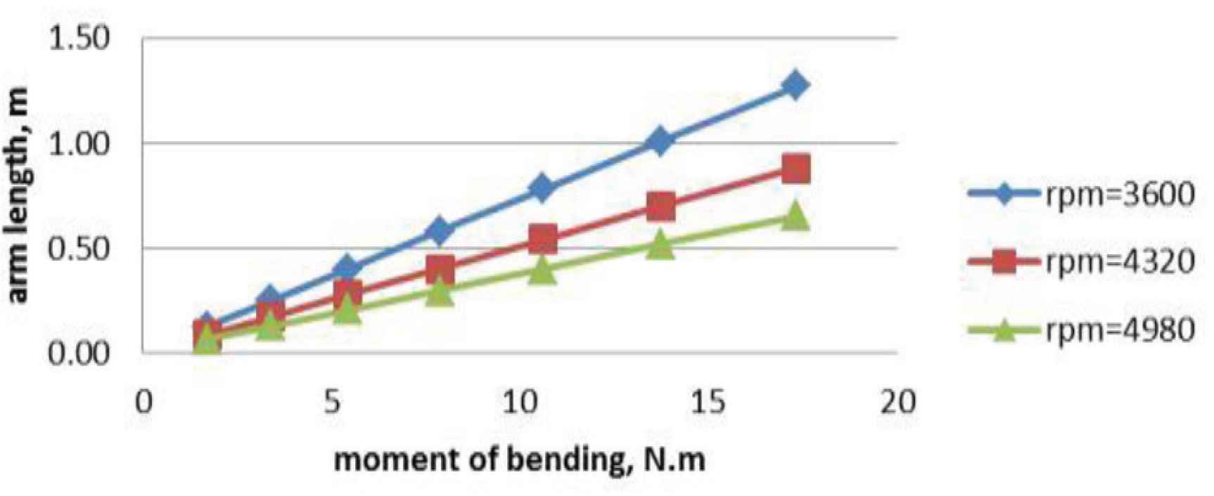
Figure 8 shows the arm length against moment of bending for three different rotor speeds 3600, 4320 and 4980 RPM. In the graph, we can see that the arm length is proportional to the moment of bending. Additionally, the slope showing in the graphs differs from each other. The slope of the rotor speed of 3600 RPM is highest compared to two other rotor speeds, 4320 and 4980 RPM. Rotor speeds of 3600, 4320 and 4980 RPM generate thrust output of 13.63, 19.71 and 26.58 N respectively Tables 3–5.
Graph arm length against moment of bending.
| Rotor version | Voltage [V] | Propeller size | Thrust [N] | RPM [Rev/Min] | Moment [N.m] | Lnew [m] |
|---|---|---|---|---|---|---|
| 13.63 | 3600 | 1.69 | 0.12 | |||
| 13.63 | 3600 | 3.37 | 0.25 | |||
| KDE5215XF-435 (435 KV) | 18.5″ × 6.3 | 13.63 | 3600 | 5.45 | 0.40 | |
| 14.8 V (4S) | KDE-CF185-DP | 13.63 | 3600 | 7.88 | 0.58 | |
| KDEXF-UAS75HVC | 16.8 V (MAX) | DUAL-BLADE | 13.63 | 3600 | 10.63 | 0.78 |
| S.R.ENABLE | 13.63 | 3600 | 13.77 | 1.01 | ||
| 13.63 | 3600 | 17.34 | 1.27 |
Data of arm length for required moment of bending (3600 RPM)
| Rotor version | Voltage [V] | Propeller size | Thrust [N] | RPM [Rev/Min] | Moment [N.m] | Lnew [M] |
|---|---|---|---|---|---|---|
| 19.71 | 4320 | 1.69 | 0.09 | |||
| 19.71 | 4320 | 3.37 | 0.17 | |||
| KDE5215XF-435 (435 KV) | 14.8 V (4S) | 18.5″ × 6.3 | 19.71 | 4320 | 5.45 | 0.28 |
| KDEXF-UAS75HVC | 16.8 V (MAX) | KDE-CF185-DP | 19.71 | 4320 | 7.88 | 0.40 |
| S.R.ENABLE | DUAL-BLADE | 19.71 | 4320 | 10.63 | 0.54 | |
| 19.71 | 4320 | 13.77 | 0.70 | |||
| 19.71 | 4320 | 17.34 | 0.88 |
Data of arm length for required moment of bending (4320 RPM)
| Rotor version | Voltage [V] | Propeller size | Thrust [N] | RPM [Rev/Min] | Moment [N.m] | Lnew [m] |
|---|---|---|---|---|---|---|
| 26.58 | 4980 | 1.69 | 0.06 | |||
| 26.58 | 4980 | 3.37 | 0.13 | |||
| KDE5215XF-435 (435 KV) | 14.8 V (4S) | 18.5″ × 6.3 | 26.58 | 4980 | 5.45 | 0.21 |
| KDEXF-UAS75HVC | 16.8 V (MAX) | KDE-CF185-DP | 26.58 | 4980 | 7.88 | 0.30 |
| S.R.ENABLE | DUAL-BLADE | 26.58 | 4980 | 10.63 | 0.40 | |
| 26.58 | 4980 | 13.77 | 0.52 | |||
| 26.58 | 4980 | 17.34 | 0.65 |
Data of arm length for required moment of bending (4980 RPM)
In order to generate moment of bending of 1.69–17.34 N.m with rotor speed of 3600 RPM, we need to increase the arm length from 0.12 to 1.7 m. For 4320 RPM rotor speed, the arm length needs to be increased from 0.09 to 0.88 m. For rotor speed of 4980 RPM, the arm lengths needs to be increased from 0.06 to 0.65 m in order to generate moment of bending of 1.69–17.34 N.m. It shows that lower thrust output or lower rotor speed requires longer arms to produce sufficient moment.
10. RESULT OF SOLIDWORKS MOTION SIMULATION
Figure 9 shows the moving arm moving inside the fixed arm.
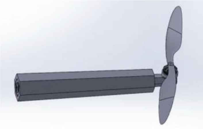
Arm moves inside the fixed arm.
This occurs when the stepper rotor rotates counter-clockwise thus the moving arm moves in negative x-direction. Figure 10 shows that the moving arm is move outside the fixed arm. This motion occurred when the stepper rotor rotates clockwise and achieved positive linear motion (forward motion).
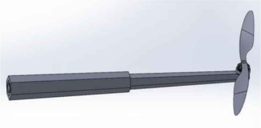
Arm move outside the fixed arm.
11. CONCLUSION
By using the mathematical analysis, the varying in arm lengths affects the moment of bending of the quadrotor. Increasing the arm length changes the moment of bending of the quadrotor to increase or decrease the arm length will decrease the moment of bending. The speed of rotor is kept at constant so that the thrust generated by the propeller rotation is at constant. The analysis also proves that the change in mechanism of the existing UAV’s quadrotor that is the quadrotor flight direction can be obtain by increasing or decreasing rotors speed. The existing methods have been extended to varying the speed of the rotor, the quadrotor flight direction can be controlled by varying the length of the quadrotor’s arms.
CONFLICTS OF INTEREST
The authors declare they have no conflicts of interest.
AUTHORS INTRODUCTION
Dr. M. Rizon
 He graduated Doctor of Engineering at Department of Computer Science and Intelligence System in Oita University, Japan. He was a Professor of Biomedical Technology in King Saud University, Saudi Arabia in 2010. He served at MIEC, Fuzhou University, China in 2019. Currently, he is a Professor of Department of Electrical and Electronics, UCSI University, Malaysia. MIET, MIEM member.
Dr. C.K. Ang
 He received his Bachelor of Engineering Degree with First Class Honors in Mechatronic Engineering from University of UCSI, Malaysia in year 2010. In end of year 2010, He was attached with Universiti Putra Malaysia for his PhD in Mechanical and Manufacturing Engineering and graduated in year 2014. Currently, he is the Dean for Faculty of Engineering Technology and Built Environment, UCSI University. He is interested in artificial intelligence, soft computing, robotics, and mechatronics. He has published many papers which related to the application of Artificial Intelligence in recent years.
Dr. Mahmud Iwan Solihin
 He is an assistant professor in mechatronics engineering department, specialized in applications of artificial intelligence/machine learning, optimizations, control systems, robotics and automation. His current research interest is mainly on applications of AI (artificial intelligence) and optimization algorithms in various filed including robotics, control systems, spectroscopy applications, sensor networks, etc., toward sustainable engineering development in the future.
Dr. Zuradzman Mohamad Razlan
 He received his PhD in Energy Mechanical System Engineering from Mie University, Japan in 2012. He is currently an Associate Professor of Mechanical Engineering Department at School of Mechatronic Engineering, University Malaysia Perlis, Malaysia. He has 11 years experiences in industrial research and development of air conditioning system and registered as Professional Engineer.
Dr. Hazy Desa
 He received his Bachelor of Mechanical Engineering from Tokushima University, Japan. He was a Senior Design Mechanical Engineer in R&D Sony Technology Malaysia in 1997. In 2001, he was employed by Tamura Electronics Malaysia. He pursued his PhD at the Artificial Life and Robotics Laboratory, Oita University, Japan in 2003. He is a Professor, Director of Center of Excellence for Unmanned Aerial System at University of Perlis. IEEE, IET member.
Dr. Shahriman A. Bakar
 He received his B. Eng., M. Eng., and PhD degrees in Mechanical engineering from Mie University, Mie, Japan. His PhD research on human and robot collaborative tasks. He is currently an Associate Professor in UniMAP Malaysia researching in system design for automotive and transportation system and currently he is leading Motorsport Technology Centre of Excellence to develop hybrid motorcycle for MITI.
Dr. Wan Khairunizam
 He received his B. Eng. degree in Electrical & Electronic Eng. from Yamaguchi University and PhD in Mechatronic Eng. from Kagawa University, in 1999 and 2009, respectively. He is currently an Assoc. Professor for Mechatronic Engineering, University Malaysia Perlis, Malaysia.
Dr. Zunaidi Ibrahim
 He received his B.Eng., M.Eng. and PhD degrees in Mechanical Engineering from Mie Univ, Japan in 1997, 2003 and 2006, respectively. Currently, he is leading a Sustainable Advanced Manufacturing research group at University Sunderland, to support TRL5-8 for SMEs company in the UK. His research interest is in machine learning in the area of a bio-medical robotic application for a sustainable manufacturing environment.
REFERENCES
Cite this article
TY  - JOUR
AU  - M. Rizon
AU  - C.K. Ang
AU  - Mahmud Iwan Solihin
AU  - Zuradzman Mohamad Razlan
AU  - Hazy Desa
AU  - Shahriman A. Bakar
AU  - Wan Khairunizam
AU  - Zunaidi Ibrahim
PY  - 2020
DA  - 2020/06/03
TI  - Effects of Variable Arm Length on UAV Control Systems
JO  - Journal of Robotics, Networking and Artificial Life
SP  - 91
EP  - 97
VL  - 7
IS  - 2
SN  - 2352-6386
UR  - https://doi.org/10.2991/jrnal.k.200528.004
DO  - 10.2991/jrnal.k.200528.004
ID  - Rizon2020
ER  -