
Design of a Data-Driven Controller with Evaluating Controller Performance
- DOI
- 10.2991/jrnal.k.190220.011How to use a DOI?
- Keywords
- PID controller; controller assessment; data-driven controller; least squares method
- Abstract
Data-driven controller systems have been proposed to achieve the desired control performance without using any system identifications. The effectiveness of these control schemes has been shown through experimental results. For time-variant and nonlinear systems, it is important to evaluate the controller performance and redesign controller when the performance is poor. According to the proposed scheme, the controller performance calculator and controller design are integrated using only input and output data.
- Copyright
- © 2019 The Authors. Published by Atlantis Press SARL.
- Open Access
- This is an open access article distributed under the CC BY-NC 4.0 license (http://creativecommons.org/licenses/by-nc/4.0/).
1. INTRODUCTION
In most industries, it is very important to get desired control performance. Data-driven control schemes [1–4] have been proposed to achieve the aforementioned desired control performance without using any system identifications. For time-variant systems, performance-driven controller [5] has been proposed to improve the steady state control performance only when the performance is poor. However, performance-driven controller cannot evaluate the transient state because this scheme focuses on the variance of steady state error.
In this paper, the scheme of evaluating controller performance without using any system identifications is proposed. According to the proposed scheme, the control performance is evaluated system output error including transient state. Furthermore, the controller performance and controller parameters are simultaneously calculated using only input and output data.
2. OUTLINE FIGURE OF THE PROPOSED SCHEME
The schematic figure of the proposed control system is shown in Figure 1. C(z−1), G(z−1), Gm(z−1), and Ĝ(z−1) are the controller, controlled system, reference model and estimated system model, respectively.
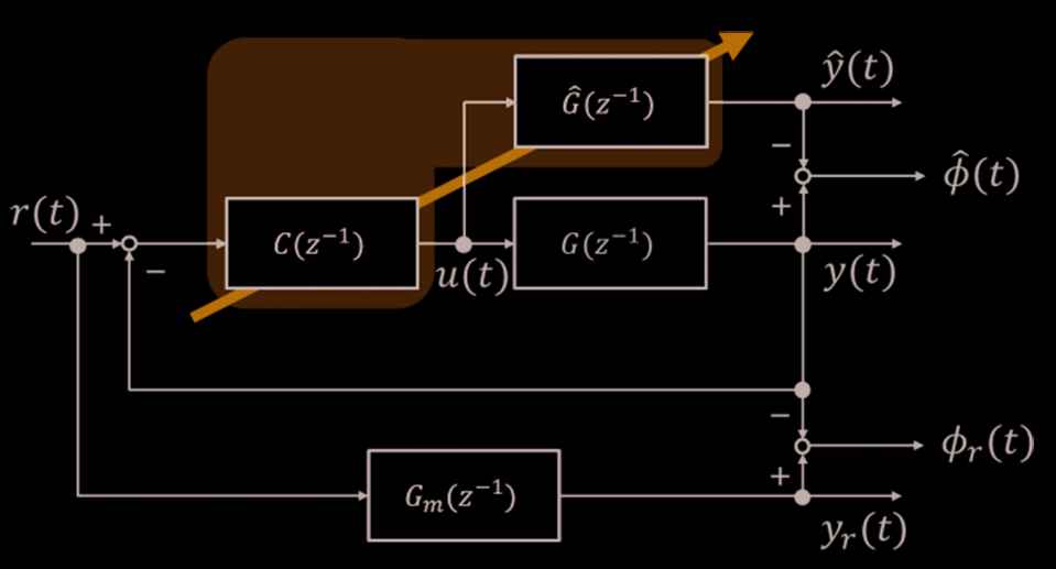
Schematic figure of the proposed control system.
The purpose of the proposed control system is to achieve the desired control performance by minimizing the following criterion Jr [Equations (1) and (2)]:
Another purpose of the proposed scheme is to design the estimated system model Ĝ(z−1) by minimizing the following Equations (3) and (4):
In addition, users set a desired reference model expressed by the following Equations (5) and (6):
3. RELATIONSHIP BETWEEN CONTROLLER AND ESTIMATED SYSTEM MODEL
The following Equation (9) can be obtained by introducing the optimized controller C*(z−1) which achieves ϕr (t) = 0:
The controlled system G(z−1) is expressed as follows by using the aforementioned Equation (10):
Here, the following estimated system model Ĝ(z−1) is defined using a controller C(z−1) instead of C*(z−1) because it is difficult to obtain the optimized controller C*(z−1) [Equation (11)]:
Note that the estimated controlled system Ĝ(z−1) is expressed using a controller C(z−1) and reference model Gm(z−1) without any system identifications.
Ĝ(z−1) equals to G(z−1) when the optimized controller C*(z−1) is obtained. It mentions that
3.1. Evaluation of the Controller Performance
The optimized controller C*(z−1) makes
3.2. Tuning Scheme of the PID Gains
In this paper, the controller is utilized as following I-PD controller [Equations (12) and (13)]:
The estimated system model Ĝ(z−1) is expressed by using I-PD controller is as follows [Equation (14)]:
The estimated output is calculated as follows [Equation (16)]:
Therefore, the PID gains are calculated by using the following least squares method [Equations (19) and (20)]:
4. NUMERICAL EXAMPLE
The controlled system G(s) is given as follows [Equation (21)]:
The parameters of the reference model Gm (z−1) are set as follows [Equation (22)]:
Finally, the initial PID gains are set as follows [Equation (23)]:
In this section, the following three simulations are shown.
- A)
Figure 2: Control result by using initial PID gains of Equation (23).
- B)
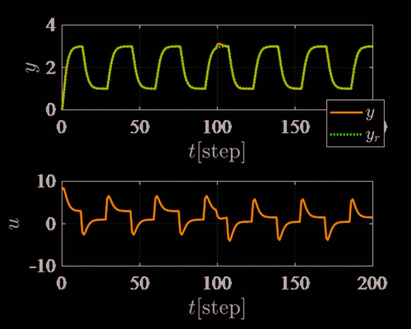
Figure 3: Control result of the proposed scheme without controller retuning.
- C)
Figure 5: Control result of the proposed scheme with controller retuning.
4.1. Control Results
Figure 2 shows the control result by using initial PID gains of Equation (23). The control performance is poor because control output y(t) does not track to reference output yr(t).
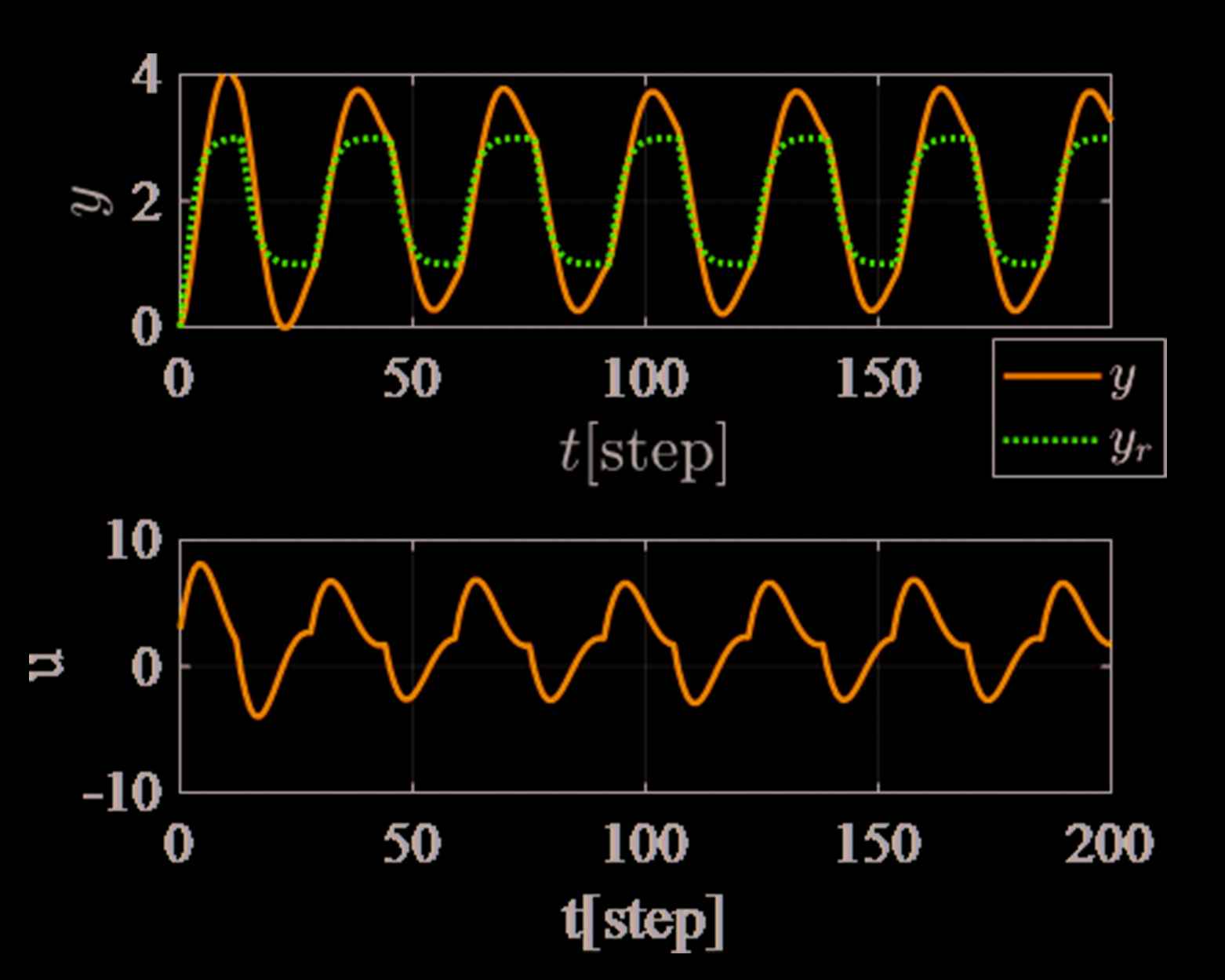
Control result by using the initial PID gains.
Figure 3 shows the control result of the proposed scheme. The following PID gains [Equation (24)] were calculated applying Equation (19) by using the data between t = 0 and 100 [step] in Figure 2:
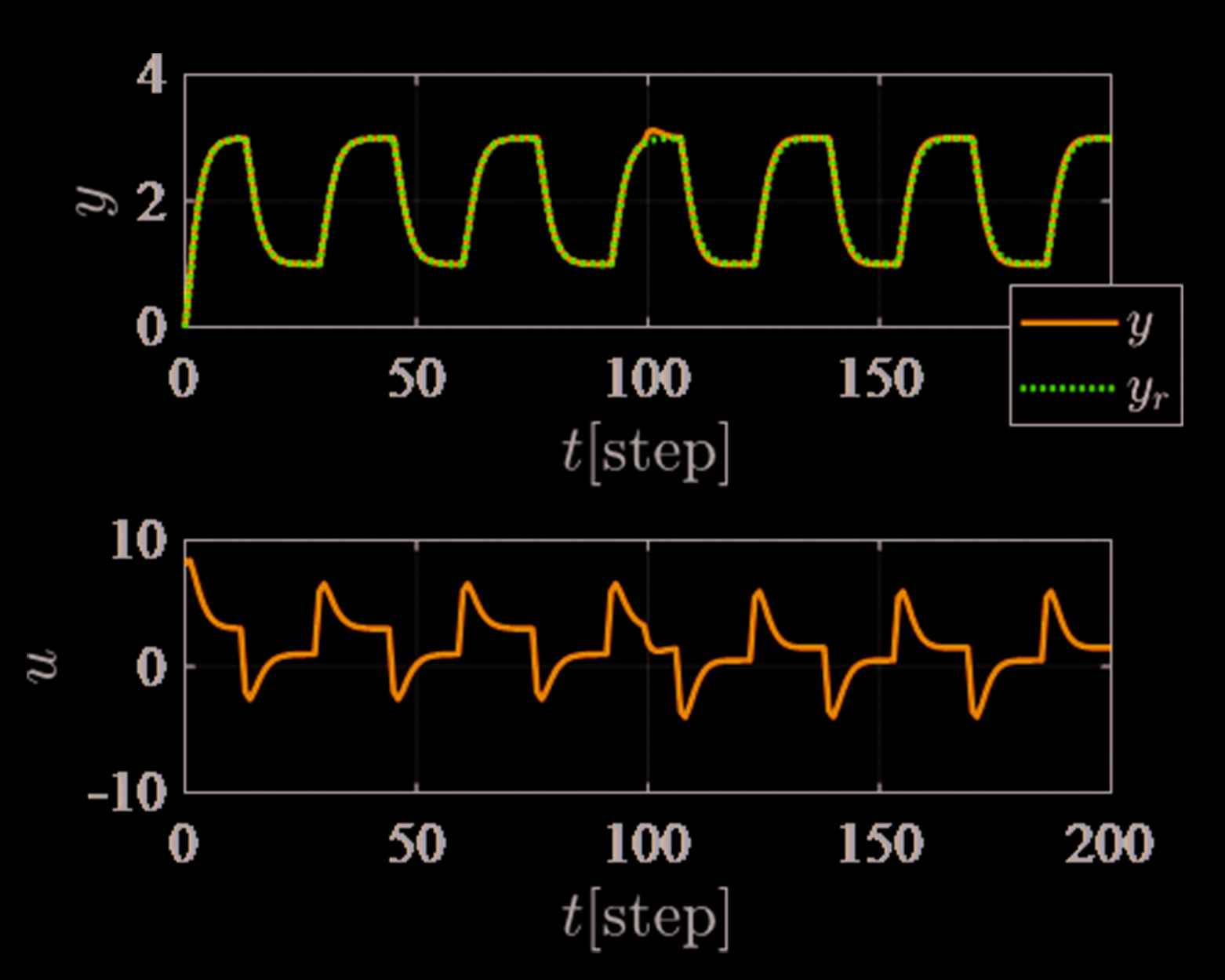
Control result of the proposed scheme without controller retuning.
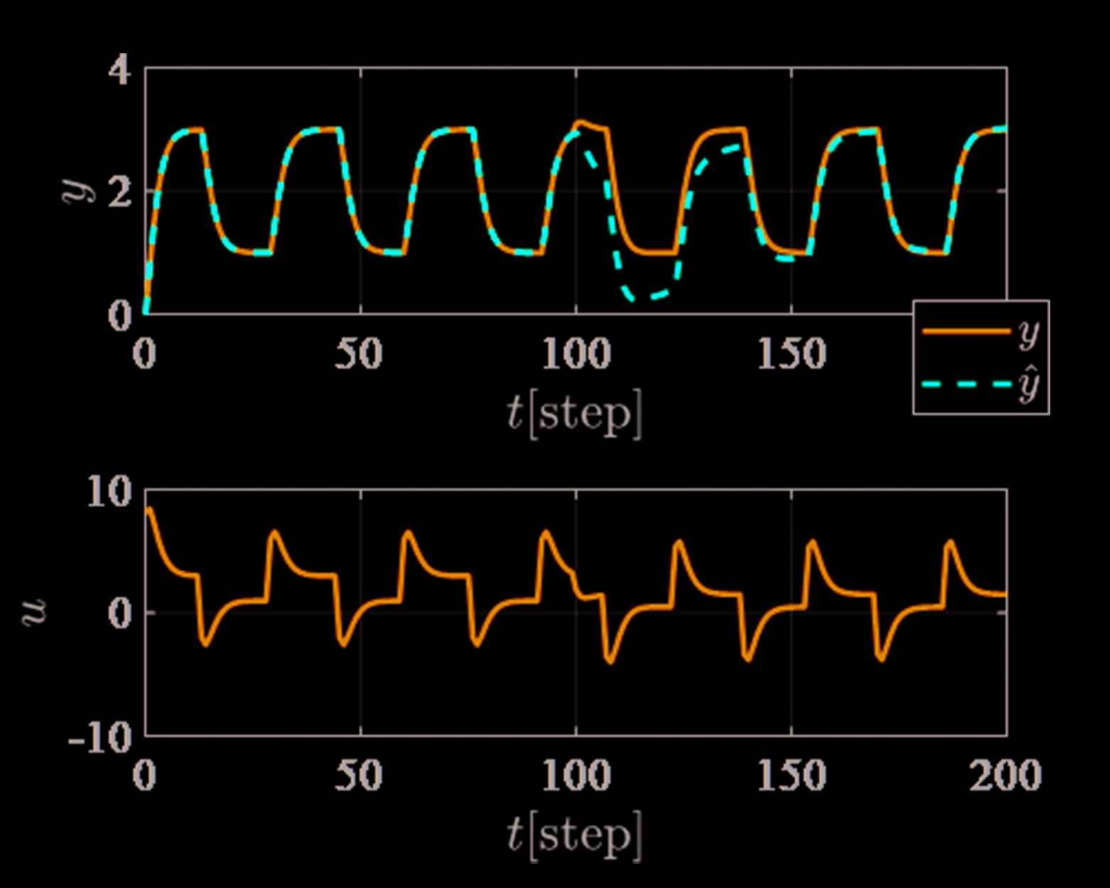
In Figure 3, the control performance is good even though the system G(z−1) is changed at t = 100 [step]. It mentions that it is difficult to detect the system parameters are changed. The reason for the abovementioned, the feedback controller C(z−1) has an integrator, and it can reduce the steady state error. On the other hand, Figure 4 shows the trajectories of the estimated output ŷ(t). It easier to detect the system parameters are changed than Figure 3.
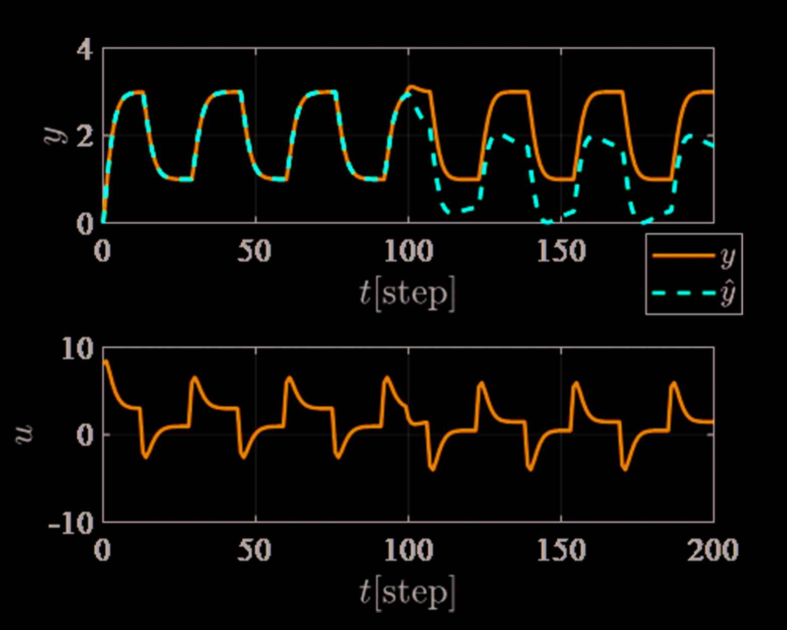
Trajectory of the estimated output ŷ(t) corresponding to Figure 3.
Finally, Figure 5 shows the control result with controller retuning at 120 [step]. Figure 6 shows the estimated output ŷ(t), and Figure 7 shows the trajectories of the PID gains corresponding to Figure 5. In Figure 7, each PID gains are slightly adjusted, however, the estimated output ŷ(t) of Figure 6 is significantly improved. Therefore, the proposed scheme can diagnose the system parameters are changed strictly.
Control result of the proposed scheme with controller retuning at 120 [step].
Trajectory of the estimated output ŷ(t) corresponding to Figure 5.

Trajectories of the PID gains corresponding to Figure 5.
5. CONCLUSION
This paper has proposed the design of data-driven control system with evaluating controller performance. The features of the proposed scheme are as follows:
- •
Controller and estimated system model can be designed simultaneously.
- •
Controller performance is evaluated by the error between output y(t) and estimated output ŷ(t) without using any system identifications.
The proposed scheme has been verified by numerical examples.
Authors Introduction
Dr. Takuya Kinoshita
 He received his B. Eng., M. Eng., and D. Eng. from Hiroshima University in Japan in 2013, 2015, and 2017, respectively. He was postdoctoral fellow of JSPS (Japan Society for the Promotion of Science) in 2017. He is currently an Assistant Professor with the Department of System Cybernetics, Graduate School of Engineering, Hiroshima University, Japan. His research interests are performance driven control.
Prof. Toru Yamamoto
 He received the B. Eng. and M. Eng. degrees from the University of Tokushima, Tokushima, Japan, in 1984 and 1987, respectively, and the D. Eng. degree from Osaka University, Osaka, Japan, in 1994. He is currently a Professor with the Department of System Cybernetics, Graduate School of Engineering, Hiroshima University, Japan. He was a Visiting Researcher with the Department of Mathematical Engineering and Information Physics, University of Tokyo, Tokyo, Japan, in 1991. He was an Overseas Research Fellow of the Japan Society for Promotion of Science with the University of Alberta for six months in 2006. His current research interests are in the area of data-driven control, and process control. Dr. Yamamoto was the recipient of the Commendation for Science and Technology by the Minister of Education, Culture, Sports and Technology in 2009.
REFERENCES
Cite this article
TY  - JOUR
AU  - Takuya Kinoshita
AU  - Toru Yamamoto
PY  - 2019
DA  - 2019/03/30
TI  - Design of a Data-Driven Controller with Evaluating Controller Performance
JO  - Journal of Robotics, Networking and Artificial Life
SP  - 257
EP  - 260
VL  - 5
IS  - 4
SN  - 2352-6386
UR  - https://doi.org/10.2991/jrnal.k.190220.011
DO  - 10.2991/jrnal.k.190220.011
ID  - Kinoshita2019
ER  -