
Practice of Control Education by Experiment using Robot
- DOI
- 10.2991/jrnal.2018.5.3.10How to use a DOI?
- Keywords
- Control education; robot; feedback control; practical education
- Abstract
In this paper, while control engineering replete with mathematical content is difficult for a beginner to learn, it is a practical branch of learning where the control theories expressed by mathematical equations prove useful only after being put into practice. However, the current status of students’ interest and curiosity in this regard is not favorable based on the impression that by learning the mathematical content only it is not possible to comprehend its actual use in practice. Accordingly, this study proposes an educational method for control systems utilizing robots, with the purpose of developing tools for inculcating interest and curiosity in students on contents such as automatic control and proportional-integral-differential (PID) control. The usefulness of the developed tools is also verified.
- Copyright
- © 2018 The Authors. Published by Atlantis Press SARL.
- Open Access
- This is an open access article under the CC BY-NC license (http://creativecommons.org/licences/by-nc/4.0/).
1. INTRODUCTION
In the advanced industrial society of the present day, society is becoming increasingly global and rapid development in science and technology and significant changes in industrial structure are taking place. Moreover, in recent years, computer (based) control is being used in various fields spurred by the development in computer technology. Accordingly, control engineering has become highly important in Japanese industry making it necessary to train instructors capable of providing control education. Moreover, control technology is being used in almost all equipment, starting from the most familiar things such as air conditioner, electric pot, and cars to others such as robots, airplanes, and spaceships. Furthermore, starting from 2012, “measurement and control using programs” is being taught as a part of Junior High School curriculum. Accordingly, many studies aiming to enhance control education have been reported [1,2].
However, since control engineering replete with mathematical content is difficult for a beginner to learn, and proves useful only when the control theories expressed by mathematical equations are actually put into practice, it is a field where experiments bridging the classroom lectures with practical learning smoothly become indispensable. In teaching control engineering, although the method of learning the use and usefulness of control theory through simulation on computers is being taught in many universities such as ours and also in vocational high schools, the current status of the students’ interest and curiosity in this regard is not favorable based on the impression that learning the mathematical content only, it is not possible to comprehend its actual use in practice. Moreover, in the high school curriculum guidelines (1) on “industry” in “subjects established mainly in vocational departments,” the subject areas include “electronic measurement control,” in which study of control basics involving electronic measurement control overview, sequence control, feedback control, and computer control is included. Accordingly, in industrial high schools, handling of feedback control and sequence control is indispensable [3]. Therefore, to inspire interest and curiosity in students, it is considered desirable that learning involves not only classroom lectures but also experiments. However, most of the experimental equipment for control is large-scale, and also very expensive, making it difficult to perform experiments involving only a few individuals.
Accordingly, in this paper, teaching materials have been developed with the purpose of use in classroom practice, to facilitate learning the different operations in manual control, automatic control, and PID control through experiments utilizing robots.
2. CONTENT ON MEASUREMENT AND CONTROL DESCRIBED IN THE GUIDELINES FOR TEACHING HIGH SCHOOL
In teaching classes on control, although knowledge of the content being taught is a must, to achieve smoother and more developmental teaching, it is desirable that the teacher possesses even deeper technical knowledge on the content taught. It is therefore necessary to develop a curriculum for students in teacher training universities based on curriculum guidelines. In the section on industry in the high school curriculum guidelines, the content related to control and the items covered have been described as follows in “Section 24 Electronic measurement control and other topics.”
- (1)
Outline of electronic measurement control.
- (2)
Sequence control.
- (3)
Feedback control.
- (4)
Basics of computerized control.
Moreover, with respect to incorporating the aforementioned content, the need to facilitate a comprehensive understanding of measurement technology, automatic control technology, and computer technology is also mentioned. In sequence control, basics of sequence control, instruments used in sequence control, and use of basic circuitry and programmable controller are covered, and the aim is to make the students conversant with knowledge and technology of sequence control. Here, the representative devices used in sequence control such as switch, relay, and timer, along with the types, applications, and logical elements of sensors used for detecting physical quantities such as light, temperature, and force are also listed. Also, the need to enable the students understand the corresponding feature, function, characteristic, and symbols used, and use them in practice is mentioned. In feedback control, the basics of feedback control, control characteristics, and the use of feedback control are covered, and the aim is to make the students conversant with knowledge and technology of feedback control. Here, the representative feedback control applications such as process control and servo control are listed, and the need to enable the students understand the respective overviews and use them in practice is mentioned.
3. EDUCATIONAL ROBOT TEACHING MATERIALS
Figure 1 shows the overall image of teaching materials using robots. The robot can throw ping-pong balls. The robot is equipped with motor for throwing the ping-pong ball, tachometer to measure the speed of the motor, and distance measuring (GP2Y0E03) for determining the distance over which the ping-pong ball is thrown. This robot can throw the ping-pong ball to insert it into the goal by controlling the motor revolutions per minute (RPM) in accordance with the distance determined by GP2Y0E03.
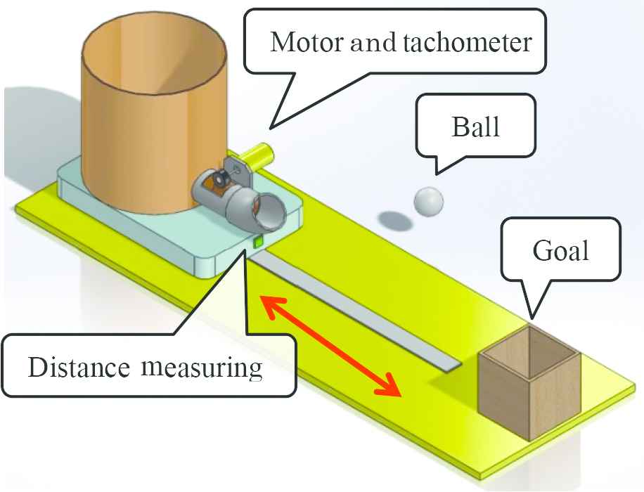
Control teaching materials robot
3.1. Precautions for Production
The following aspects were considered in producing the robot.
- (1)
Can be produced inexpensively.
- (2)
No special parts are used.
The reason for this is to enable building a number of such devices inexpensively, so that they can be utilized easily in actual educational settings. Moreover, this is also easy to enable replacement of parts as the devices may malfunction with repeated use.
Figure 2 shows the external appearance of the robot. This robot uses parts purchased at 100 yen shops, and the total cost of parts per robot is about 5000 yen.
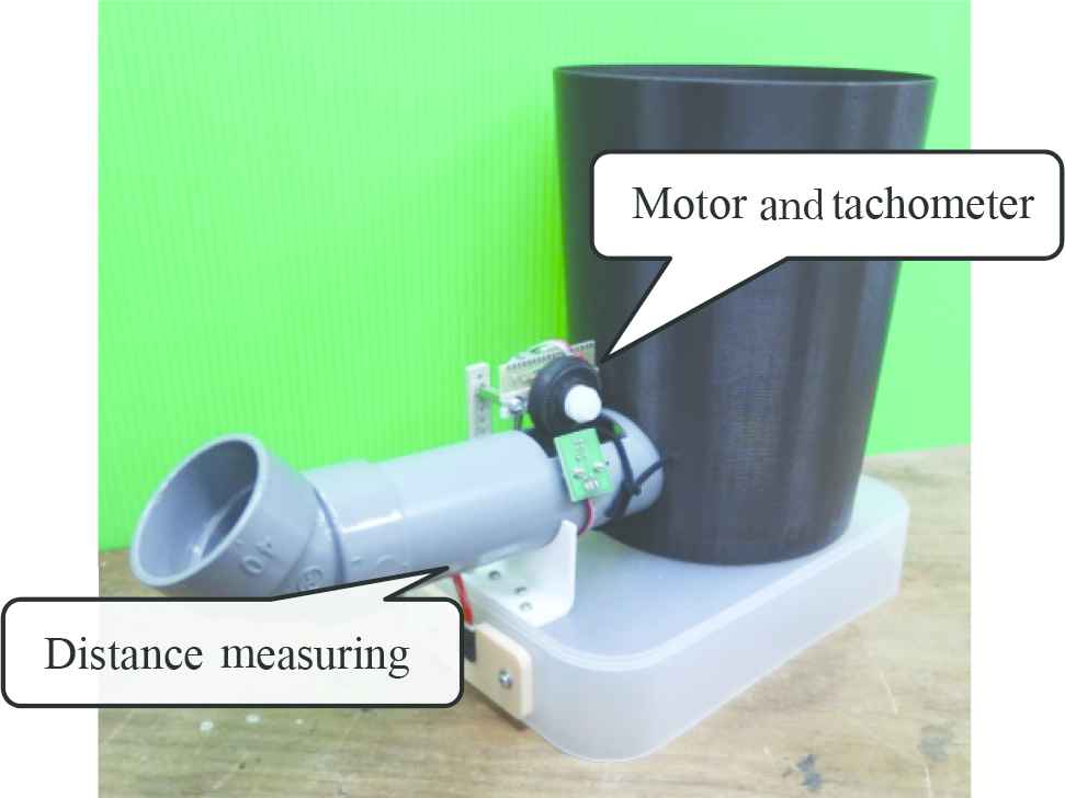
Robot
3.2. Hardware
Figure 3 shows the robot circuitry used in the hardware configuration. The computer used was Arduino Uno Rev3 (Next, Arduino). Using this computer, the input to the motor is calculated using the operation command and information from the sensors. Arduino is used by connecting it to a personal computer. The PC displays the input, the output results, and the various gains.
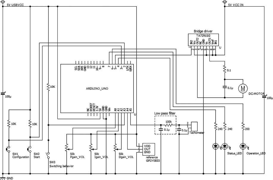
Circuit
Moreover, as shown in Figure 4, volumes are attached to the circuit board for adjusting the various gains. Additionally, a switch has also been installed for switching between manual and automatic control modes.
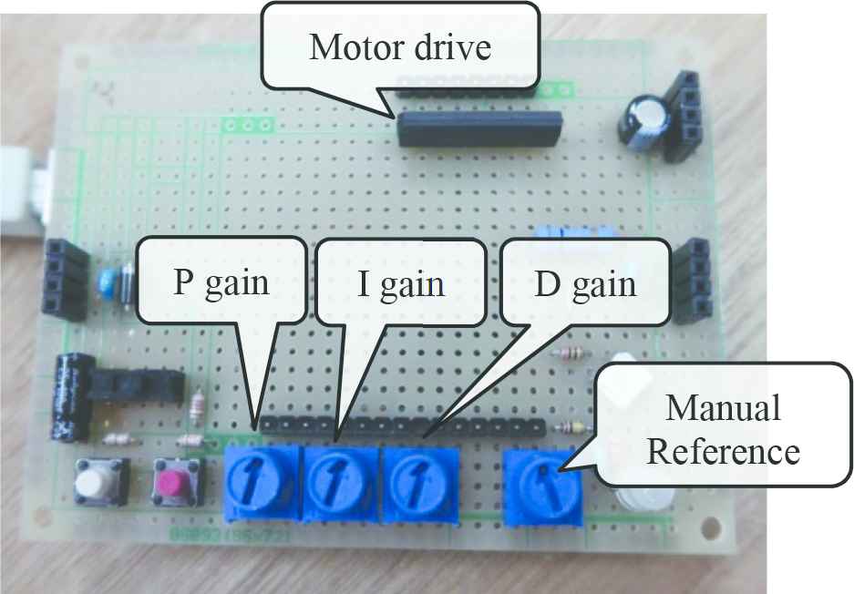
Operation unit
3.3. Software
Arduino, using its function for 10-bit resolution of analog electrical voltage input, produces a number (integer) in the range of 0–1023. The output voltage is controlled by pulse width modulation (PWM). The output using 8-bit resolution specifies a number (integer) in the range of 0–255, thus changing the duty ratio. The duty ratio is 0% when the number is 0, 50% when the number is 128 and 100% when the number is 255.
The rotor RPM is calculated using the following Eq. (1), based on the tachometer output voltage.
4. EXPERIENCE CONTENTS
The hands-on training is conducted using the robot. The specific educational content of the experiments are as follows:
- (1)
Difference between manual and automatic control.
- (2)
Difference between ON–OFF and PID control.
- (3)
How to adjust the PID gain of automatic control?
Consider the block diagram as shown in Figure 5. However, r(t) is the target value, y(t) is the output, and e(t) is the deviation (=r(t) − e(t)) between the target value r(t) and the output value y(t). u(t) is the input (manipulated variable).
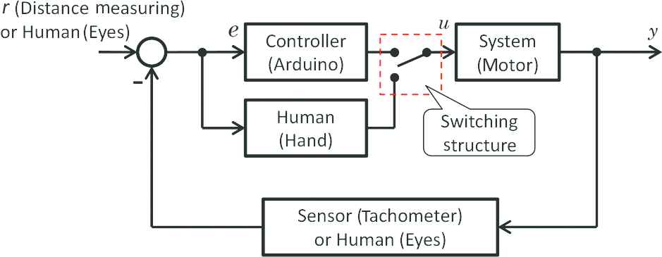
Block diagram
4.1. Control Tuning
Learn that by using simple ON–OFF control, it is not possible to control accurately in the sense of perfectly matching the target value. With respect to the control result, teach the aspect that not only the output but also the input observation are important. ON-OFF control is expressed by the following Eq. (2).
Design a proportional controller and give an appropriate proportional gain Kp to observe the output. P control is expressed by the following Eq. (3).
The PI control is expressed by the following Eq. (4).
PID control is expressed by the following Eq. (5).
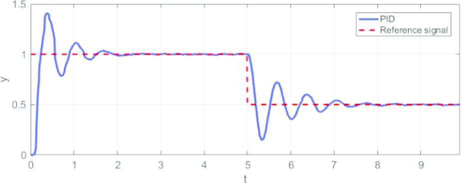
Gain unadjusted result
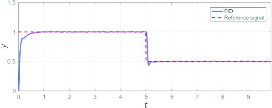
Gain adjusted result
5. CONCLUSION
In this paper, teaching materials were developed so that usefulness of measurement and control can be actually experienced. As a result, manual and automatic control of the rotor could be realized. It is hoped that further improvement can be realized in the future through setting of challenges such as taking into account equipment trouble, and setting difficulty level in hands-on training.
ACKNOWLEDGMENT
The authors thank by Prof. A. Yamada from the Tokyo Gakugei University for his valuable comments.
Authors Introduction
Dr. Shinichi Imai
 He graduated doctor course at Department of Engineering in Hiroshima University. He works at Department of Education in Tokyo Gakugei University. His research area is about control system design, educational engineering.
Mr. Hideto Matsui
 He graduated master course at Department of Education in Tokyo Gakugei University. He works at National Institute Technology. He is interested in control education.
REFERENCES
Cite this article
TY  - JOUR
AU  - Shinichi Imai
AU  - Hideto Matsui
PY  - 2018
DA  - 2018/12/01
TI  - Practice of Control Education by Experiment using Robot
JO  - Journal of Robotics, Networking and Artificial Life
SP  - 190
EP  - 193
VL  - 5
IS  - 3
SN  - 2352-6386
UR  - https://doi.org/10.2991/jrnal.2018.5.3.10
DO  - 10.2991/jrnal.2018.5.3.10
ID  - Imai2018
ER  -