
A Study on the Lumbar Burden Evaluation of Work using One Smartphone
- DOI
- 10.2991/jrnal.2018.5.3.7How to use a DOI?
- Keywords
- Smartphone; lumbar burden; gyro sensor; state estimation; acceleration sensor; JACK
- Abstract
In this paper, we propose the human lumbar burden evaluation method and state estimation system using a smartphone and an application on agricultural work. The proposed system consists of two functions: (1) “State estimation” has a function of estimating posture (Stand up, Sit down, Crouch, Walk, etc.,) of the subjects, (2) “Lumbar burden estimation” has a function to estimate the angle of the waist from the angle of the subject’s upper body and calculate the lumbar burden in combination with other parameters. The aim of this paper is to get the data of the subject’s work status in the agricultural field in a simple manner and quasi-real time and help improve the agricultural work efficiency by constructing the agricultural work burden evaluation system were using a smartphone. In this paper, we show on the experimental results of two functions and the evaluation of the actual agricultural work.
- Copyright
- © 2018 The Authors. Published by Atlantis Press SARL.
- Open Access
- This is an open access article under the CC BY-NC license (http://creativecommons.org/licences/by-nc/4.0/).
1. INTRODUCTION
In recent years, agricultural workers in Japan have decreased and aging rapidly so it is necessary to review the physical environment of agricultural work. One solution to reduce this problem, technological developments has been made to reduce the burden of agricultural workers and automation various agricultural machinery. On the other hand, quantitative comparison of how much newly developed agricultural machinery reduces the burden of conventional agricultural work is difficult.
Also, it is difficult to measure whether the compressive force of the lumbar intervertebral disc during these agricultural workings (hereinafter, lumbar burden) exceeds the lumbar burden allowance value 3400 N at work labor defined by the National Institute for Occupational Safety and Health (NIOSH). Therefore, paying attention to the burden of the lumbar area, the purpose of this thesis is to construct a work burden evaluation system to evaluate whether the burden reduction rate due to IT conversion of agricultural machines and the lumbar burden during agricultural work do not exceed 3400 N.
To construct the system, we used a smartphone equipped with various sensors such as acceleration sensor, gyro sensor. This paper examines whether the proposed system can be realized with one smartphone. As related research [1–5], there are the lumbar burden of construction workers [1,2], walking measurement in the home [3], walking measurement and posture estimation using smartphones [4,5]. However, all of these studies are indoor studies, and in the study of construction workers it is not an estimation of the lumbar burden of a state with heavy working machines such as agricultural work.
Also one of the burden analysis software has what is called JACK [6,7]. JACK can create a digital human being as a virtual human by manual input on the desktop, assign work and assign dynamic burden analysis. JACK creates a digital human in a stationary state as shown in Figure 1, adds external force, and can evaluate the burden of that state. However, as a problem of JACK, the burden cannot be measured either in real time or continuously, so estimation of a lumbar burden with JACK is unsuitable in agricultural work. For related research [8,9], there is research to estimate the burden of the waist when carrying objects using JACK. However, these studies are simple transport tasks, not simulations of complex cases such as walking with farm equipment during agricultural work. In this thesis, we compared it with measured value in JACK for judging whether the fixed posture is correct.
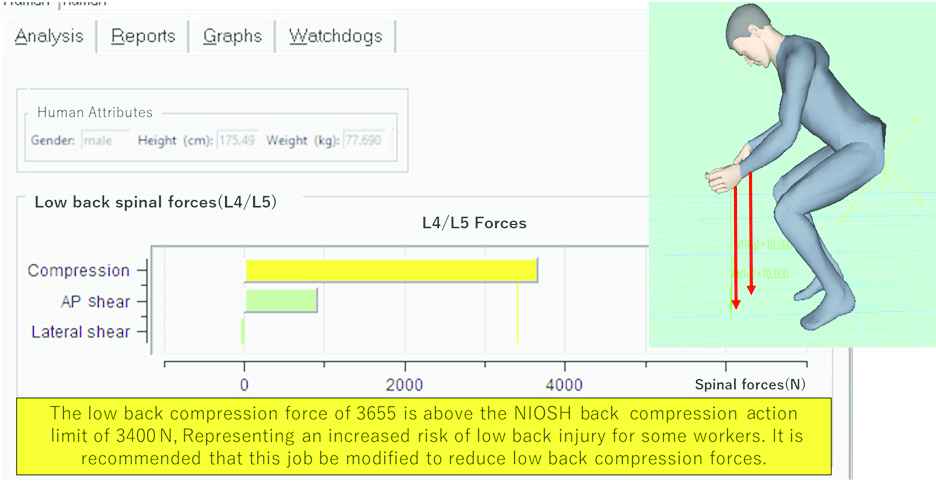
Digital human model (JACK version 6.1) and lumbar compression analysis function
In this paper, we investigate whether the estimation of the lumbar burden in agricultural work is possible. To do the investigation, we compare the case of using the automatic mowing machine with remote controller and the case of using the mowing machine. The user’s state is judged with one smartphone. There are five kinds of user’s state judgment: stand, walking, crouching, sitting and rotation. Figure 2 shows the target states of five patterns to be determined.
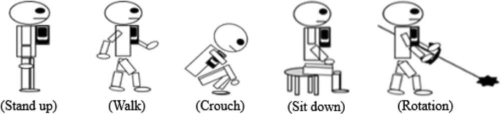
Five kind of state judgment to be judged
2. PROPOSED METHOD
In this chapter, we describe the method of estimating the loads that can be determined by the state and the estimated lumbar burden using a smartphone.
2.1. Determination of Mounting Position
In this section, the installation position of the smartphone is explained. In this research, the smartphone to be used is attached to the chest pocket (Figure 3). There are two reasons for that. First, it is possible to judge the condition of walking, sitting, squatting, turning, the second is to be able to calculate the waist angle.

Installation position of the smartphone
2.2. Calculate Waist Angle
To evaluate the lumbar burden, the pressure of lumbar intervertebral disc calculated from the waist angle and knee flexion angle. At this time, the waist angle can estimate from the device inclination angle (upper body angle) of the smartphone attached to the breast pocket. But knee flexion angle cannot estimate of the smartphone attached to the breast pocket. The knee flexion angle can calculate from the thigh inclination angle. Hence, it is necessary to make the constant thigh inclination angle when it is determined operation. Nevertheless, since the way of walking and crouching is different depends on the person, it is impossible to determine obviously the inclination angle of the thigh. Therefore, prior to conducting the experiment, the thigh inclination angle in the walking, rotation, and crouching is confirmed beforehand and used as the input information. The upper body angle is α, the waist angle is β, and the thigh inclination angle is γ, which is shown in Figure 4. The waist angle was calculated as in Eq. (1).
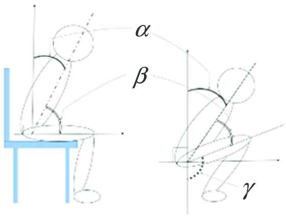
Three angles used for calculation of lumbar burden
The inclination angle of the device is calculated from the gravitational acceleration obtained by the acceleration sensor (Figure 5). The device inclination angle (slope angle θ) shown in Figure 6 and its calculation formula is shown in Eq. (2). In addition, gravY and gravZ are defined as the gravitational acceleration of Y- and Z-axis. The unit is degree.
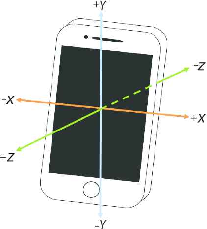
Axial direction of the acceleration sensor
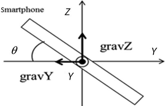
Tilt angle of the device in the direction of gravity
2.3. Lumbar Burden Estimation Method
In this section, we explain the method of estimating the lumbar burden. The lumbar burden estimation formula is shown in Eq. (3).
The meaning of each parameter is as follows: Fc: lumbar burden (N), Uw: weight above the waist (kg), g: gravitational acceleration (m/s2), Rar: inclination angle of the joint surface of the lumbar vertebrae and the sacrum (rad), Lw: load of object (kg), Fa: abdominal pressure (N), Fm: spinal column standing muscle force (N). The waist angle and the knee flexion angle are calculated from the body inclination angle previously input according to the state of the subject and the body angle calculated from the acceleration data of the smartphone. Substitute these two angles into Eq. (3) and seek the lumbar burden.
In the lumbar burden estimation during rotation, it is necessary to consider not only the thigh inclination angle but also the waist burden in the transition of rotation of the waist. Therefore, JACK was used to calculate the transition in the lumbar burden during rotation. Table 1 shows the change in the lumbar burden during rotation in JACK at the average height and weight [height 172 (cm), weight 67 (kg)] of 30-year-old Japanese general male.
| Rotation angle (°) | 0 | 10 | 20 | 30 | 40 |
| Lumbar burden (N) | 384 | 387 | 386 | 391 | 393 |
Transitions in the lumbar burden accompanying waist rotation with JACK measurement
From the JACK measurement results, there was an increasing tendency in the transitions of the lumbar burden during rotation, but the change was small. Therefore, the burden due to the rotation of the waist has not been introduced.
2.4. Algorithm for State Determination
The flowchart of the smartphone that attached on the breast pocket can be seen in Figure 7.
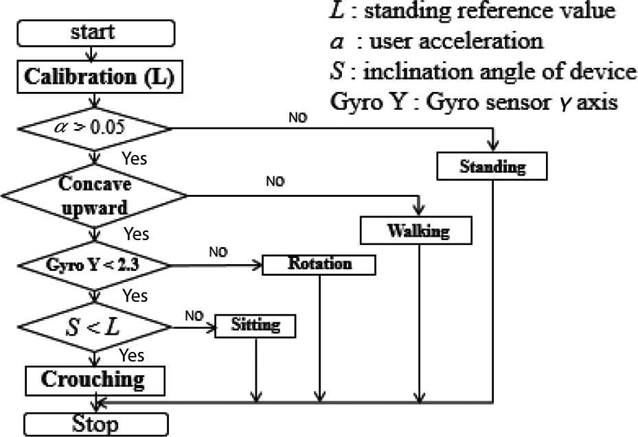
Algorithm flowchart
Subject attaches the smartphone to the breast pocket, and resting for a few seconds in a standing state. The criterion value L (°) of the subject’s state is determined after performing calibration. The α is defined the moving average of the vector composite value of acceleration X, Y, Z given by the user with 20 data. It assume that the case where α exceeds the threshold value 0.05 is in operation. The operation is a state that waiting for determination of walking, rotation, crouching, and sitting. When gyro sensor Y-axis exceeds 0.06 (rad/10 ms), the state turns to the rotation. In addition, when the angle of the device is below a certain value during the operation. This means in a crouching or sitting state. When it is judged that the tilt angle of the device is stabilizes after the smartphone goes down has been measured, the case where the tilt angle S (°) of the device is equal or more than −15 (°) of the judgment value it is assumed to be sitting, the exception is crouching.
2.5. Identification of Walking and Rotation
In this section, we explain the method of identification of walking and rotation. In order to identify walking and rotation, not only an acceleration sensor but also a gyro sensor capable of recognizing rotational motion is used (Figure 8).
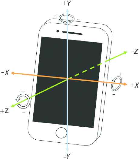
Axial direction of gyro sensor
2.5.1. Determination of threshold
In this section, we describe the method of setting the threshold value in the rotation determination. Since a person performs an action involving rotation while walking, a gyro sensor indicates a reaction. Therefore, it is necessary to identify the state of walking and rotation. So we conducted preliminary experiments to extract feature points from walking and rotation motion. In this experiment, walking (three steps) and rotation (three times) actions were performed twice on eight subjects. After completion of the experiment, check the value of the gyro sensor Y-axis used for the rotation determination and obtain the threshold value. Experimental results of one subject as an example are shown in Figure 9.
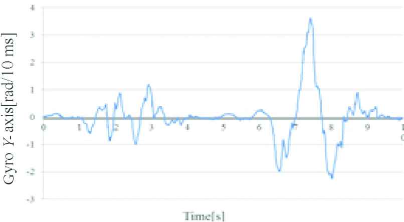
Transition in gyro sensor Y-axis during walking and rotation
From Figure 9 the average value of the gyro sensor Y-axis is about 1.0 (rad/10 ms) during walking and about 2.5 (rad/10 ms) during the rotation determination. Therefore, the average of amplitude values of the gyro sensor Y-axis at the initial operation of walking and rotation determination of all 16 data is obtained. The threshold value is determined from the average of the values. The result is shown in Figure 10.
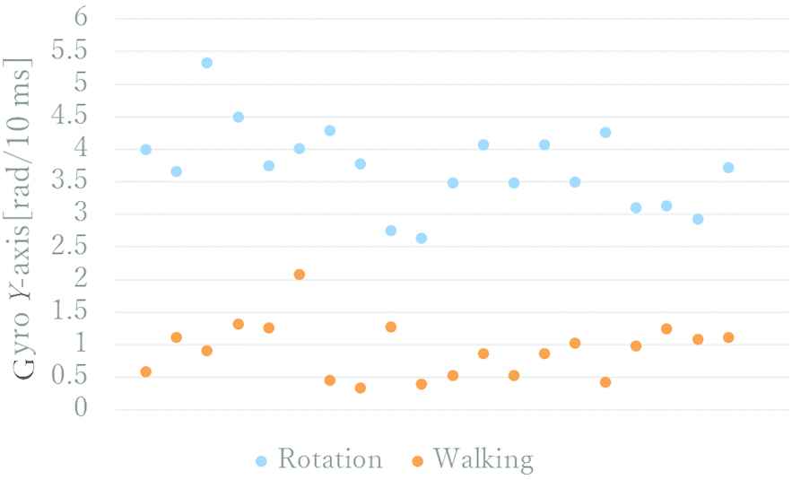
Amplitude values of walking and rotation
The average amplitude value in walking was about 0.92 (rad/10 ms), and the average amplitude value in the rotation was about 3.72 (rad/10 ms). It was judged that the difference between the average of these two operations was sufficiently large, and the average of the two values was 2.32 (rad/10 ms) as the threshold in the rotation determination.
2.5.2. Verification experiment
In this section, we explain the accuracy verification experiment of walking and rotation determination. To distinguish walk determination and turn determination, two subjects were wearing a smartphone in the chest pocket and performed two movements, walking (six steps) and rotation (six times), and verify the threshold value set this time is adequate. The subject stands for 1 s between the walking motion and the rotation motion. Take a picture of the experiment with a video camera and confirm whether it is identified by synchronizing from the taken video and smartphone data. The experimental result of one subject is shown in Figure 11.
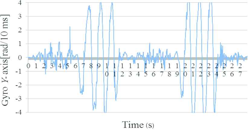
Value of gyro sensor in walking and rotation
Figure 12 shows the state determination. The vertical axis shows the state judgment result, and the horizontal axis shows time.
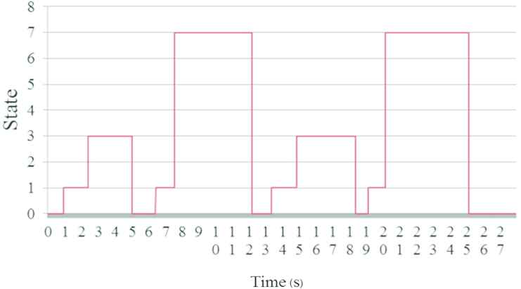
State determination in walking and rotation
State 0 is standing judgment, states 1, 2, and 6 are state judging, state 3 is walking judgment, state 4 is sitting judgment, state 5 is crouching judgment, and state 7 judged rotation. The actual operation time by the subject is the time in Figures 11 and 12, the walking time is 1–5 s, 13–18 s, the rotation time is 6–12, 19–25 s. When the value of the gyro sensor Y-axis exceeds the threshold value 2.32 (rad/10 ms) from the result of Figure 12, it is understood that the rotation determination is performed. As a result of the experiment, it is possible to distinguish walking and rotation.
3. EXPERIMENTAL CONDITION
In this chapter, we describe the two methods. There are the experiments verification, the performance verification of the state determination and accuracy verification of the compression force of the lumbar intervertebral disc.
3.1. Performance Experiment of State Determination
In this section, we describe the experimental method of the performance verification of the state determination to estimate lumbar burden. The state determination is necessary for estimating lumbar burden is performed using the thigh inclination angle in each state measured on each subject. This experiment was conducted three times on eight subjects. Subjects work in the order of standing, walking (six steps), rotation (six times), stumbling (one time), sitting (one time). The interval between each motion is 3 s. The motion at that time was recorded with a video camera, and the motion in the movie was taken as a true value. The analysis method compares the state determination (smartphone value) determined by the application installed in the smartphone with the true value, and calculates the identification rate when the determination is made. The calculation method of the identification rate is shown in Eq. (4).
3.2. Estimation Accuracy of Lumbar Intervertebral Pressing Force
Experimental tools are one smartphone, a mowing machine (5.5 kg), and an automatic mowing machine (80.0 kg). Automatic mowing machine operates by the remote controller (0.5 kg). The method is to wear a smartphone in the breast pocket of the subject and get them to do farm work freely. We record that motion with a video camera and confirm the moving state from this video data. In this experiment, the burden analysis software JACK 6.1 version (JACK) was use for comparison. JACK is the software that can create virtual human on the desktop manually, allocate work to that virtual human, and can analyze its dynamic burden. We create a digital human model with the agricultural attitude, the load of the subject in the movie taken during the experiment, and calculate the lumbar burden. The calculated value taken is a true value.
4. RESULTS
In this chapter, we describe the result verification method. There are the experiments verification, the performance verification of the state determination and accuracy verification of the compression force of the lumbar intervertebral disc.
4.1. Result of State Determination
In this section, we describe the experimental results of the performance verification of state determination. Table 2 indicates the action (Action) actually performed by the subject, the motion estimation (Estimation) by the proposed method, and its identification rate.
| Action | ||||||
|---|---|---|---|---|---|---|
| Standing | Walking | Rotation | Crouching | Sitting | ||
| Estimation (%) | ||||||
| Standing | 100 | 14.9 | 0 | 2.8 | 29.5 | |
| Walking | 0 | 61.2 | 0 | 0 | 0 | |
| Rotation | 0 | 0 | 86.3 | 0 | 5.6 | |
| Crouching | 0 | 0 | 0 | 85.3 | 4.5 | |
| Sitting | 0 | 0 | 8.4 | 0 | 26.9 | |
| Else | 0 | 31.3 | 13.3 | 16.1 | 40.7 | |
| Total | 71.9 | |||||
Distinguish rate of state determination
From Table 2 we can see that the overall identification rate was 71.9%. The identification rate of walking and sitting state judgment was bad, and the identification rate of the rotation and crouching judgment was good.
4.2. Result of Lumbar Intervertebral Pressing Force
In this section, we describe the experimental result of the verification accuracy estimation of the lumbar intervertebral disc pressing force. The lumbar burden estimation result during using mowing machine indicated in Figure 13a and automatic mowing machine indicated in Figure 13b The vertical axis represents the lumbar burden (N), and the horizontal axis represents time (min).
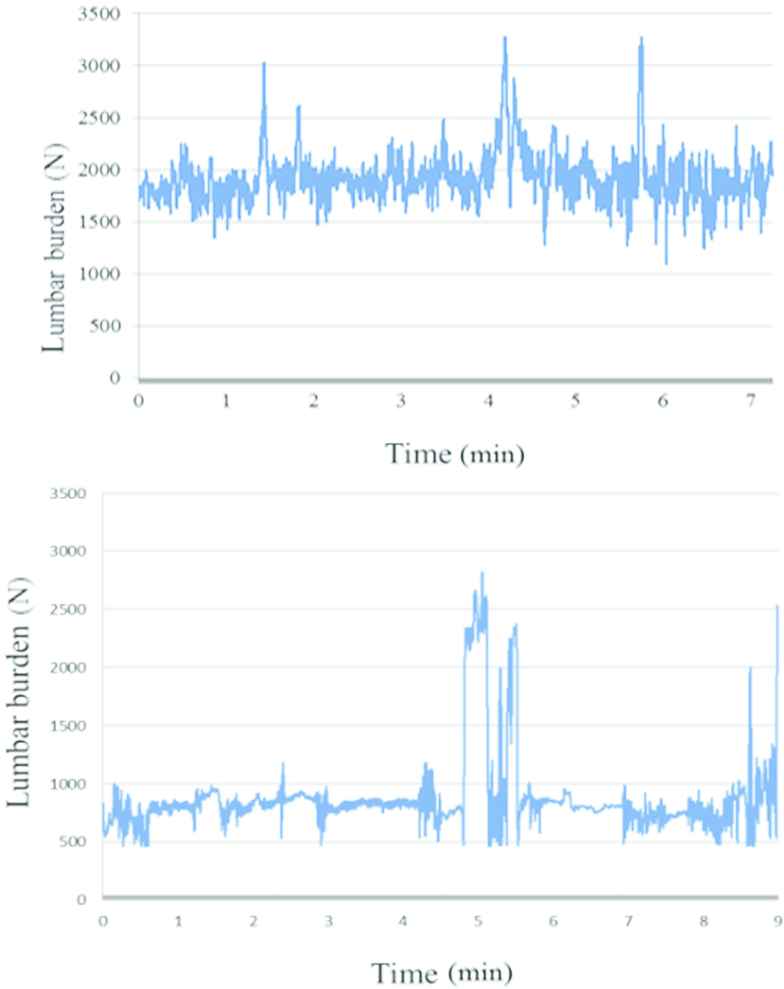
(a) Lumbar burden estimation graph (mowing machine). (b) Lumbar burden estimation graph (automatic mowing machine)
From the results in Figure 13a, the maximum value was 3278 N, the minimum value was 749 N, and the average value was 1704 N. During using the automatic mowing machine, the maximum value was 2820 N, the minimum value was 484 N, and the average value was 882 N. The reason why the lumbar burden was increased around 5 min in Figure 13b was because the condition judgment came in the Crouch as the subject performed the setting of the automatic mowing machine. The reason that the lumbar burden is increased around 9 min is because the smartphone shakes when taking out the smartphone from the subject’s chest pocket.
4.3. Comparison with JACK
In comparison with the JACK, JACK measurement used Figure 14 as a digital human model.
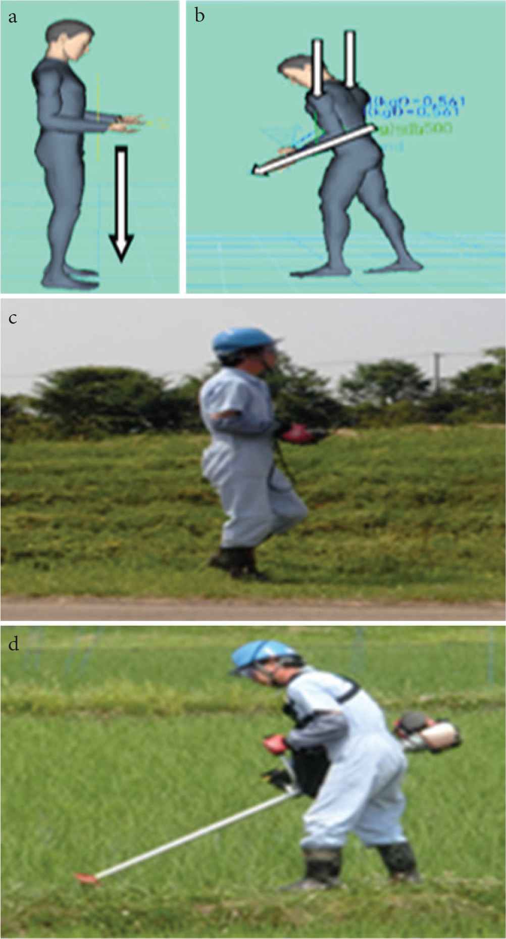
(a) Automatic mowing machine (JACK). (b) Mowing machine (JACK). (c) Automatic mowing machine. (d) Moving machine
To compare with JACK, we first create a digital human with the subject of this experiment as a model. Manually reproduce the subject’s posture while using the automatic mowing machine and while using the mowing machine for the created digital human. The external force exerted on the subject is added to the human model to analyze the lumbar burden in JACK and compare with the proposed method. Figure 14a indicates that the image which using the automatic mowing machine and Figure 14b shows that the image which using the mowing machine. In addition, Figure 14c shows a digital human model created with Figure 14a and d shows a digital human model created with Figure 14b.
The arrow in the image represents the direction of the force. At the time of remote control operation, 0.5 kg force applied to the hand in the direction of gravity, and it is necessary to distribute the weight of 5.5 kg during mowing operation. Therefore, we are applying 4 kg to the shoulder and 1.5 kg to the arm. The momentary lumbar burden calculated under the above conditions, and the result showed in Table 3.
| Smartphone (N) | JACK (N) | Error (N) | Error rate (%) | |
|---|---|---|---|---|
| Automatic mowing machine | 549 | 526 | 23 | 4.37 |
| Mowing machine | 1202 | 1394 | 192 | 13.77 |
Comparison the result of smartphone and JACK
Although the error between smartphone measurement result and the JACK measurement result which using the remote controller was small, the error in the result of the mowing machine was large.
5. CONCLUSION
In this thesis, verification of the state determination estimation and the lumbar burden estimation method in agricultural work were conducted using one smartphone.
Regarding the state determination, identifying the state judgment estimate of five patterns with 71.9% is possible. However, the identification rate average result of walking and sitting determination got worse. Walking determination depended on state determination about 30%. The reason for this worsening is that since the state determination is performed using the moving average of 20 data in the identification of the walking determination, a time lag occurs. Also, in the sitting determination, there was a lot of misrecognition as the standing determination and the state during determination. We consider that the reason is because the tilt angle used for standing and sitting determination is calculated with a close value. In addition, based on the estimation result of the lumbar burden of agricultural work by the proposed method, we found that the lumbar burden with the automatic mowing machine was about 800 N lower than that of one with the mowing machine. Hence, the lumbar burden with the automatic mowing machine burden was reduced.
Moreover, we also found that the lumbar burden does not exceed the allowable value 3400 N of the lumbar burden at the time of agricultural work defined by NIOSH. From this result, we can say that there is a possibility that the proposed method can be used for evaluating the lumbar region burden of agricultural work.
According to the comparison result by JACK, the error between the smartphone measurement value and the JACK value at the time of using the automatic mowing machine was small. The error between the smartphone measurement value and the JACK value at the time of using the mowing machine became large. This is because the proposed method differs from the JACK measurement calculation method in that the skeleton of the subject of the JACK measurement is different from the proposed method. Although the proposed method models the skeleton of the Japanese, JACK measurement models the skeleton of the American, so the measurement result is considered to be different.
As a future task, considering a method of calculating the lumbar burden in an action that takes into consideration the vector direction of motion at the time of agricultural work such as pulling an object and pulling a target object like a mowing machine is conceivable.
ACKNOWLEDGMENT
Thank you for Mr. Maiguma, Mr. Nonaka and Tamura Laboratory that has supported us in this study.
Authors Introduction
Dr. Hiroki Tamura
 He received his PhD from Kyushu University, Japan in 2006. He is a Professor in the Department of Environmental Robotics, Miyazaki University, Japan. His main research interests are Neural Networks and Optimization Problems. In recent years, He has the interest in Biomedical Signal Processing using Soft Computing.
Dr. Koichi Tanno
 He received his PhD from Graduate School of Science and Technology, Kumamoto University, Kumamoto, Japan in 1999. He is a Professor in the Department of Electrical and Systems Engineering. His main research interests are in analog integrated circuit design and multiple-valued logic circuit design. Dr. Tanno is a member of IEEE.
Dr. Keiko Sakurai
 She received her PhD from Interdisciplinary Graduate School of Agriculture and Engineering, Miyazaki University, Japan in 2018. She works as a researcher in Faculty of Engineering at Miyazaki University. Her main research interests are biological signal measurement systems, especially gaze estimation system.
Mr. Yasufumi Fuse
 He graduated from Nihon University School of Science and Engineering in 1991. Since 2001, he is an Engineer of Miyazaki Prefecture Industrial Technology Center. In 2008 Master’s course in Miyazaki University graduated. The main fields of research are Mechanical Engineering, Welfare Engineering, Ergonomics.
REFERENCES
Cite this article
TY  - JOUR
AU  - Hiroki Tamura
AU  - Keiko Sakurai
AU  - Koichi Tanno
AU  - Yasufumi Fuse
PY  - 2018
DA  - 2018/12/01
TI  - A Study on the Lumbar Burden Evaluation of Work using One Smartphone
JO  - Journal of Robotics, Networking and Artificial Life
SP  - 173
EP  - 179
VL  - 5
IS  - 3
SN  - 2352-6386
UR  - https://doi.org/10.2991/jrnal.2018.5.3.7
DO  - 10.2991/jrnal.2018.5.3.7
ID  - Tamura2018
ER  -