
Improving Functional Safety of Automotive Video Data Transmission and Processing Systems
 , Frank Langner2, Benjamin Axmann3, Karlheinz Blankenbach4, , Jan Bauer5, , Matthäus Vogelmann4, Manfred Wittmeir6, Sascha Xu7
- DOI
- 10.2991/jase.d.210213.001How to use a DOI?
- Keywords
- Functional safety; ISO 26262; Video data transmission / processing system; Camera monitor system (CMS); Advanced driver assistance system (ADAS); Safety-related system; Safety mechanism; Safety architecture; Safety concept; Light-to-light (L2L) protection; ASIL-prepared video communication (APV)
- Abstract
As of today, automotive video data transmission and processing systems are already being developed according to ISO 26262, but safety mechanisms and safety architectures for such systems are individually derived on a case-by-case basis. This approach, i.e., reinventing the wheel, over and over again, is neither effective nor well suited for future use cases with system variants and varying system components from multiple suppliers. Further, existing safety mechanisms for video data transmission and processing systems fall short of providing a full “light-to-light” monitoring. To reduce this gap, this paper proposes a generic safety architecture and a method to derive suitable safety mechanisms for automotive video data transmission and processing systems. In addition, enhanced safety mechanisms to detect and indicate faults in such systems are outlined. These contributions to improve the functional safety of automotive video data transmission and processing systems have been devised in a joint research project involving an automotive OEM and multiple industrial and academic partners.
- Copyright
- © 2021 The Authors. Published by Atlantis Press B.V.
- Open Access
- This is an open access article distributed under the CC BY-NC 4.0 license (http://creativecommons.org/licenses/by-nc/4.0/).
1. INTRODUCTION
In modern road vehicles, digital video data is being transmitted between multiple cameras, image processors, displays, and various electronic control units (ECUs). Examples are camera monitor systems (CMS) such as rear-view camera systems or mirror-replacement systems and advanced driver assistance systems (ADAS) such as highway or parking pilot systems. In the latter, camera-generated video data in combination with information from other sensors (e.g., radar or lidar), enables innovative ADAS capabilities. A wide range of additional video-based functions is in the plans of automotive OEMs.
An particular challenge associated with these use cases is the efficient handling of system variants and system components developed by different suppliers.
Safety is one of the key issues in the development of road vehicles. The ISO 26262 standard [1] provides guidance to achieve functional safety, i.e., to mitigate risks resulting from systematic and random failures of electric/electronic in-vehicle systems (E/E systems).
Malfunctioning transmission or processing of video data, may adversely affect the driver's ability to perform their driving task or the functionality of vehicle systems that rely on the video data. Malfunctions include frozen images, delayed images, or incorrect image transformations.
While ISO 26262 provides general guidance to mitigate the risks resulting from systematic and random failures of E/E systems, this guidance needs to be applied and interpreted in the context of the specific video data transmission and processing system under consideration.
A key activity in the development of a safety-related E/E system is a suitable system architectural design. The design shall be capable to instantiate the safety requirements allocated to the system. When deriving the system architectural design for a video transmission/processing system (abbreviated as video system in the following), the technical capabilities of the intended hardware and software elements with regard to the achievement of functional safety need to be considered. As a consequence, dedicated safety mechanisms (SMs) to detect failures need to be devised and to be implemented. Further system components may be necessary to collect the information about these failures and to control or mitigate them.
Todays' video systems are already being developed as per ISO 26262, but their safety architectures are specifically designed for each system. This approach, i.e., reinventing the wheel, over and over again, is neither effective nor well suited for future use cases with many system variants and varying system components from multiple suppliers.
For other application domains, common and reusable safety architectures have been devised. A prominent example is the standardized e-gas monitoring concept for engine control systems [7]. However, such a common safety architecture does not yet exist for video systems.
To advance the functional safety of automotive video data transmission and processing applications, the project “ASIL-prepared video systems” (APV), a joint undertaking between an automotive OEM, and multiple industrial and academic partners, was initiated in 2018. The vision of the APV project is to enable a full “light-to-light” fault protection from the initial optical to electrical conversion in the camera to the final electrical to optical conversion in the display (L2L protection) for future safety-related video systems.
As part of this project, the authors devised a generic safety architecture for automotive video data transmission and processing applications and developed a method to devise suitable SMs for video systems. Gaps identified by this method were filled with novel and enhanced SMs for such systems that can be integrated into the proposed safety architecture.
1.1. Outline
Section 2 reviews fundamentals of in-vehicle video data transmission and processing, including exemplary current and future applications and common system components. This culminates in a generic model of video data transmission and processing systems that we use as a frame of reference throughout this paper. Section 3 discusses fundamentals and normative requirements regarding functional safety. In Section 4, we provide a method to systematically evaluate SMs for fault detection and indication in video systems and show how this method can be used to support the ASIL-dependent selection of SMs for a given system. This constitutes the 1st major contribution of this paper. We also introduce enhanced display monitoring, a novel SM for fault detection, and indication in automotive video data transmission and processing systems developed to address gaps of the existing mechanisms. This constitutes the 2nd major contribution of this paper. Section 5 discusses the proposed safety architecture for such systems as an enhancement of our generic model for video data transmission and processing providing the 3rd major contribution of this paper. Section 6 describes an demonstrator-based approach used by the authors to refine and validate the proposed concepts. Finally we conclude our work in Section 7 and lay out ideas for future research.
1.2. Related Work
ISO 26262 [1] provides the normative framework for functional safety of automotive E/E systems. This standard also provides a generic fault model for data transmission, however this is not adapted to video data.
Principal considerations regarding the functional safety of CMS are outlined in [6]. Bauer et al. [3] specializes the abovementioned fault model for automotive video data transmission and processing systems and provides a set of possible safe states for such systems. Exemplary SMs for fault detection in such systems are discussed in [4,5,18].
The idea of having a generic safety architecture for a class of systems has been inspired by the so-called 3-level architecture outlined by the e-gas consortium [5]. Using patterns for safety architectures has been proposed in [11] as well.
1.3. Research Method
Gap Analysis: Based on the technical characteristics of current automotive video systems and the SMs integrated into them and relevant literature the authors collected and analyzed 40+ existing and proposed SMs for such systems. Using the analysis method discussed in Section 4.2, these SMs were systematically analyzed by the APV project partners regarding their fault detection capabilities.
Development of SMs: In parallel, existing SMs were extended and new ones were developed (see Section 4.3). This activity was inspired by the idea to provide a L2L protection of video systems, that specifically includes the electrical to optical conversion in the display. The development of enhanced and novel SMs was guided by the results of the gap analysis.
Development of a generic safety architecture: Early in the project, it turned out that the combination of many local and global SMs implemented in different system components provided by many suppliers would benefit from adhering to a set of architectural constraints. This motivated the development of the proposed safety architecture and the common message formats described in Section 5.
Proof of concept: To validate and refine the proposed ideas, a proof of concept demonstrator representing an automotive video system was implemented (Section 6). It was used to prototype, evaluate, and refine the proposed SMs and to prototype the system-level safety architecture. In addition, studies with test persons were carried out to tune parameters for the proposed SMs.
2. IN-VEHICLE VIDEO DATA TRANSMISSION AND PROCESSING
2.1. Digital Video Data Fundamentals
Digital video data consists of a stream of images I: I1, I2, I3, I4, … (Figure 1 top). The frequency at which consecutive images (also called frames) are displayed is referred as to the frame rate and expressed in frames per second (FPS).
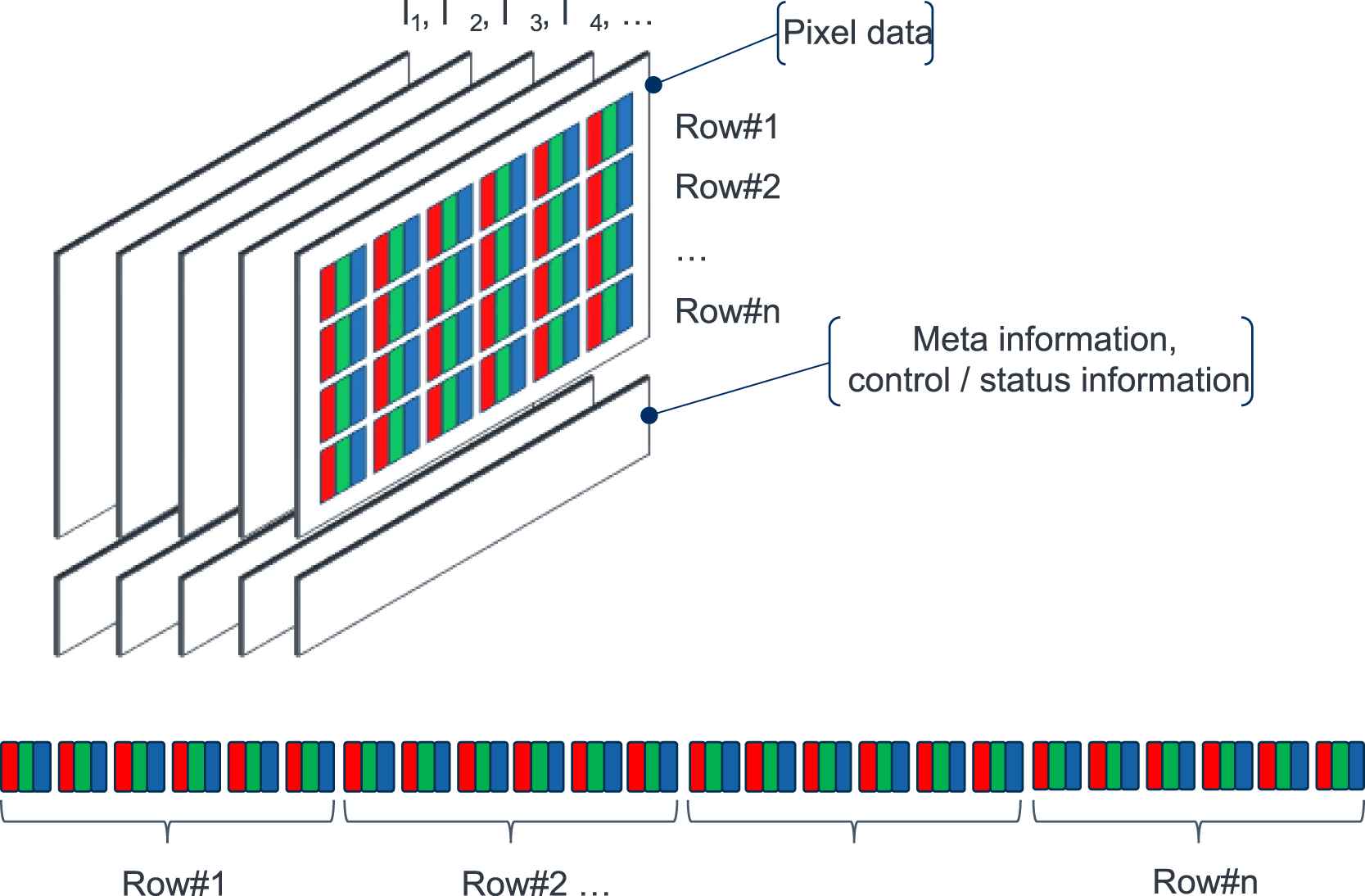
Digital video data (top) and structure of an RGB image as sequence of bytes (bottom).
An image is a rectangular tiling of fundamental elements called pixels (short for picture elements). It can be represented by a matrix of pixels (pixel data). The number of rows and columns in this matrix determines the size of the image.
A pixel is a small block that represents the amount of gray intensity of the corresponding portion of the image. For typical grayscale images, 8 bits ranging from 0 (black) to 255 (white) are used to encode the gray value of an pixel [22].
In color images, pixels can be represented by three values (R, G, B). These values indicate the intensity of red, green, and blue, respectively, needed to render the pixel on the display (RGB image, Figure 1 top). Typically 8 bits are used to encode each of the three color components. resulting in 24-bit color depth. 0 means that none of the color appears in the pixel and 255 indicates that the highest level of the color is evident in the pixel [22].
This way, digital images can be encoded as bit streams (Figure 1 bottom).
In addition to the pixel data, digital images may also comprise meta information and/or control/status information. Meta information and control/status information can be integrated into the bit streams as well, however there is no standardized way to do this.
2.2. Exemplary Applications
2.2.1. Camera Monitor Systems
CMS consist of a camera capturing a field of view (FOV), forwarding the signal to an ECU or similar component for additional processing and then using a display to visualize the information to the driver [16].1 CMS currently used in automotive applications, include rear-view camera systems and mirror-replacement systems.
Rear-view camera systems (reversing cameras systems) aid in backing up the vehicle and mitigate the rear blind spot. Such systems became increasingly popular among car buyers and even mandatory in certain markets [17].
They use special video cameras that are attached to the rear of the vehicle (Figure 2, top left). Their images are usually reproduced on the vehicle's central information display (Figure 2, top right). As the camera and the driver face opposite directions, the camera image needs to be flipped horizontally. In addition, the driver can also be assisted by image augmentation such as trajectory lines or distance estimates for close objects.
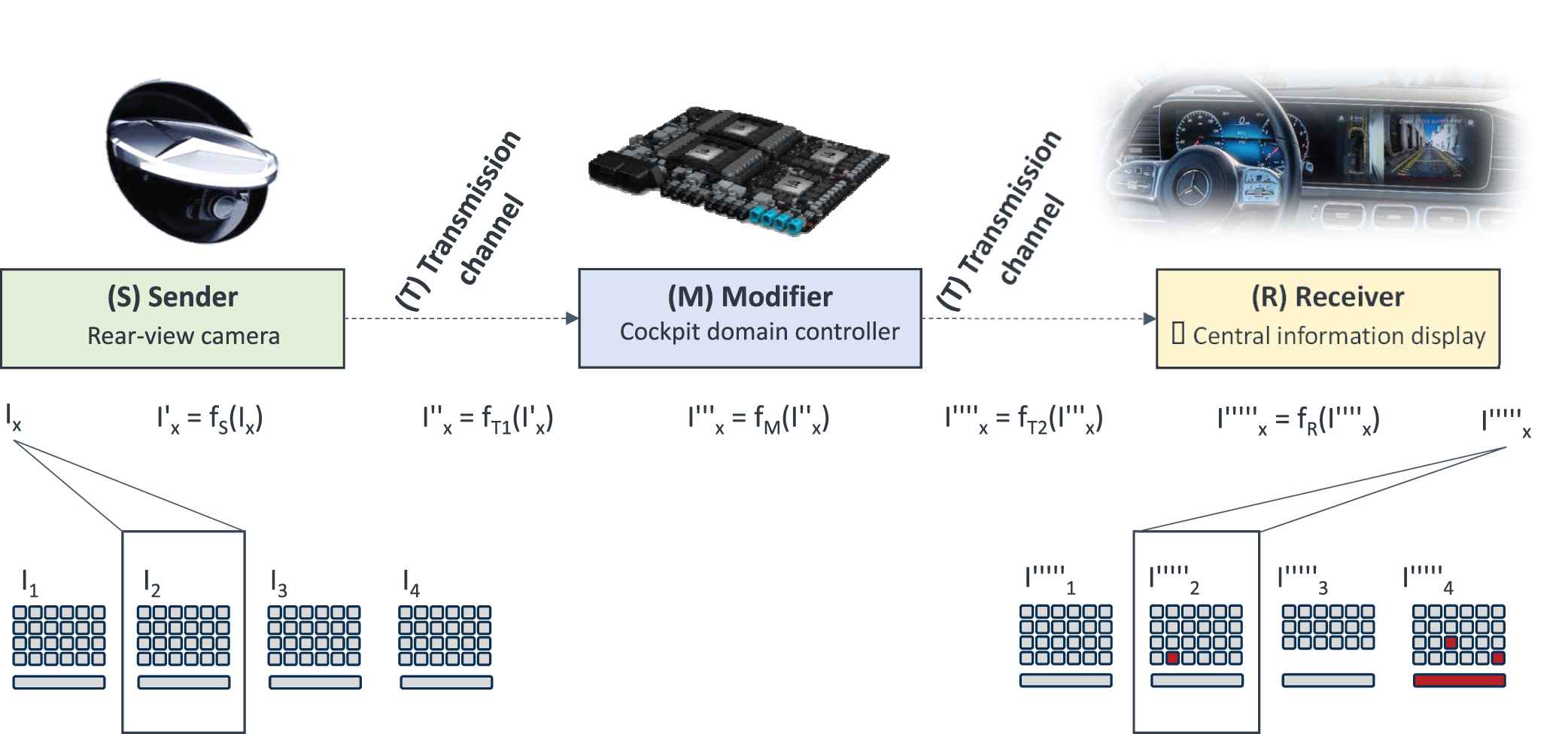
Generic model of a video data transmission and processing system.
For such systems, essential image information may not be altered or lost. As drivers rely on this information augmentation needs to be correct and shall not obstruct essential image information.
2.2.2. Video-based ADAS
Video captured by cameras can also be used as input to ADAS and fused with information obtained from other sensors, e.g., radar, lidar, or vehicle motion sensors. A prominent class of such video-based ADAS are partially automated functions that provide longitudinal and lateral guidance to the vehicle in specific situations.
As an example, current highway-assist systems use a combination of camera and radar data to take over the longitudinal and lateral guidance in monotonous driving situations on highways.
Video-based ADAS use machine learning algorithms to automatically detect objects [13] and to predict depth maps [14] in order to gain an understanding of the situation outside of the vehicle. Here the quality of the video input must be guaranteed, especially for neural network algorithms [15].
2.2.3. Future use cases
The scope of video systems is not limited to the ones discussed above. Future use cases include using the vehicle's front support pillars as displays (a.k.a. virtual A-pillars) to eliminate forward blind spots [8], and utilizing the windscreen area to display place- and object-related content on points of interest in the surrounding area with the help of augmented reality (AR) technology (a.k.a. AR head-up displays (AR-HUDs)) [9,10,20].
2.3. System Functions and Components
Despite their variety, in-vehicle video data transmission and processing applications comprise a common set of functionalities and components.
A CMS can be functionally divided into the following three essential parts [2]:
Image capturing;
Image processing; and
Image displaying.
2.3.1. Image capturing (cameras)
Image capturing is realized by cameras. Their main objective is to capture the visual surrounding field of the vehicle [2].
Cameras (see Figure 2, top left) are used to capture color images of a specific FOV. A camera mainly consists of a lens, an imaging sensor [2], and an image processing system. Frequently, the data from the camera is being transmitted to an external modifier (e.g. head unit) for further processing.
The lens collects light rays from the environment and directs them to the image sensor (imager). The imager consists of a matrix of photo sensitive pixels which are exposed by a frame rate of 60 Hz. The information is then digitized by an A/D converter to a raw image.
The raw images are then optimized in terms of color, brightness, sharpness, and white balancing to obtain high-quality digital images. The sequence of images obtained by the camera forms a video stream that is transmitted to other system components via a high-speed video interface.
Due to their superior performance, cameras are increasingly used as sensors for various ADAS. State-of-the-art automotive multi-purpose cameras have a logarithmic sensitivity characteristic (often named as HDR), a resolution of approx. 5 mega pixels and a FOV of about ±50° horizontally and ±25° vertically. Powerful image processing systems enable augmentation (e.g. trajectories for rear-view cameras) and real-time artificial intelligence methods for scene interpretation and object detection.
2.3.2. Image processing (modifiers)
The image processing transforms the captured images to provide desired display characteristics on the display unit (e.g., brightness or contrast adaptation, filtering). The image processing part may also compute necessary controls of the camera (e.g., zoom) or the display unit. It may also process user inputs and interface data from/to external ADAS [2].
As image processing components modify the images, we use the generic term modifier to refer to an image processing component.
Modifier functionality can be realized in hardware or software, either as a separate device (e.g., head unit), or integrated directly into an image capturing or displaying component [2]. An example for an integrated modifier component is an image processing capability implemented directly in a camera. Alternatively, there might be multiple modifiers located in different physical components.
As part of the image processing, modern systems may overlay the original image with additional driving-related visual information (e.g., telltales, labels, colored areas) such that part of the original information is hidden. Overlays can be partially transparent or totally opaque and can be displayed temporary or permanently [2]. As an example, overlay generators are needed to display rear-view camera images with superimposed trajectory lines.
2.3.3. Image displaying (display units)
The image displaying represents the actual computed image in the vehicle on a screen or display unit at an appropriate viewing position for the driver. It can be realized for example by a flat screen (e.g., a central information display (CID, see Figure 2, top right), or a projection (e.g. a HUD)) [2].
Displays (monitors) are devices for displaying images. They convert digital images/video data into optical light [19].
Displays may also be used to visualize operational data such as vehicle speed, the selected gear or telltales. Displayed images may differ from the captured images due to image transformations and/or augmentation carried out by modifier components.
Incoming high-speed video data (with a data rate in the range of Gbit/s) is reformatted in a flat panel display into subsequently addressed column signals. Typically, the pixel matrix is filled and refreshed at 60 Hz.
State-of-the-art display supervision monitors the supply voltages and digital signals. This approach is based on the assumption that displays show the intended content if the incoming data is correct and the display works within its limits. In case of detected major malfunctions, the display will be switched off. Selected display malfunctions that are not detected may be recognized by the driver (perceived faults). However, there are various safety-relevant faults, which are neither detected nor recognized immediately by the driver, e.g., deviations in gray level reproduction.
Last but not least, video data needs to be transmitted between system components using wired or wireless video transmission links/channels. Transmission needs to account for the pixel data as well as control/status information and the meta information.
2.4. Generic Model of a Video Data Transmission and Processing System
In the following, we utilize the generic model of a video data transmission and processing system [3] depicted in Figure 2 as a frame of reference when discussing safety aspects of such systems.
This model abstracts from the actual physical components of a specific system by introducing logical sender (S), modifier (M), and receiver (R) components, which are connected by wired or wireless video transmission channels (T).
In case of a basic back-up camera system, the digital video data that comprises pixel data and meta information is being generated by the rear-view camera as a sequence of images (I), modified by a camera-internal or external modifier, transmitted via a wired transmission link, and displayed on the infotainment display on the dashboard as a sequence of images (I''''').
In general, a system might comprise zero, one or multiple instances of each type. As an example, the camera portion of a video-based ADAS may be realized by a stereo camera system consisting of two cameras. Components might be located outside of the actual vehicle, e.g., the monitor of a remote operator.
Please note that so far the generic model does not contain any SMs or components dedicated to functional safety.
3. FUNCTIONAL SAFETY CONSIDERATIONS
Safety is a key issue in the development of road vehicles [1]. To assist the development of safety-related automotive E/E systems, the international standard ISO 26262 [1] provides guidance to achieve functional safety, i.e., to mitigate risks due to hazards caused by malfunctioning behavior of the E/E systems.
Guidance provided by ISO 26262 includes (a) technical guidance on how to implement functional safety into a product (product requirements) as well as (b) an automotive safety lifecycle to be used when developing safety-related E/E systems (process requirements).
The safety lifecycle comprises a concept phase, the system, hardware, and software development phases, as well as the production and operation phase. This paper is primarily concerned with aspects of the initial system development process.
Its main activity is the derivation of the technical safety concept (TSC), i.e., the specification of technical safety requirements (TSRs) for the video system, their allocation to system elements and associated information providing a rationale for functional safety [1].
The system architectural design is the selected system-level solution to be implemented by the video system. It shall fulfill both, the allocated TSRs as well as non-safety requirements.
The TSRs specify the technical implementation of the higher level safety requirements considering the system architectural design. A key portion of the TSRs are so-called SMs to detect faults and to prevent or mitigate failures [1]. Necessary are SMs to
Detect, indicate, and control faults in the system itself and in external components that interact with the system;
Prevent faults from being latent;
Achieve or maintain a safe state; and
Define and implement the warning and degradation strategy [1].
4. SMs FOR FAULT DETECTION AND INDICATION
As part of the APV project, the authors identified and analyzed existing SMs to detect and indicate faults in video systems.
4.1. State of the Art
SMs utilized in current automotive video systems typically check the integrity of the incoming pixel stream (pixel clock, input resolution, etc.) as well as the correctness of the incoming image data at the receiver component. Such mechanisms include but are not limited to:
4.1.1. Local pixel data checksums
The plausibility of incoming image data can be checked by using local pixel data checksums. A current implementation of this SM allows to select up to four freely definable and possibly overlapping rectangular image areas (regions of interest, ROIs). CRCs for these regions are calculated by the image generating component at the display and compared with each other [12]. A CRC mismatch indicates an image corruption in the affected ROI(s). In case of camera data, a constant CRC indicates a frozen image. Image corruptions could be detected with high diagnostic coverage (DC) (≥99% DC), the DC w.r.t. frozen images is more system-specific and depends on the nature of the video data and the selected ROIs.
Using a purely CRC based verification of incoming image data would indicate an image corruption even in the case of minimal, neglectable modifications to the pixel data. Systems with modifiers providing compression or color management, that alter the images may render such an SM useless.
4.1.2. Telltale monitoring
Telltale monitoring allows to check the correctness of essential image information such as indicator or malfunction lights displayed in known ROIs of a larger image.
This SM computes global descriptors and boundary descriptors for reference telltales stored in the display as well as for the ROI of the video stream containing the telltales. An analysis component compares the global descriptors to calculate the color and contrast difference and cross-correlates the boundary descriptors to compute a match percentage. Comparing the global descriptors provides an indication of the final contrast and the color shift. By cross correlating the boundary descriptors, a shape matching measure can be defined.
Current implementations [5] can monitor up to 20 telltales simultaneously. As the approach is based on the correlation of descriptors rather than an exact comparison of pixels, it is tolerant w.r.t. image transformations such as scaling, moderate distortion, or color manipulations.
These are just 2 examples out of ~40 existing and proposed SMs that were collected [3].
4.2. Gap Analysis
As a prerequisite to systematically evaluate the fault coverage of these SMs and to inform the selection of suitable SMs for a video system under development, the relevant failure modes (FMs) of video systems need to be identified and combined into a fault model. Such a fault model for video systems needs to consider FMs of the S, M, and R components as well as for the transmission channel (lightning bolts in Figure 3).
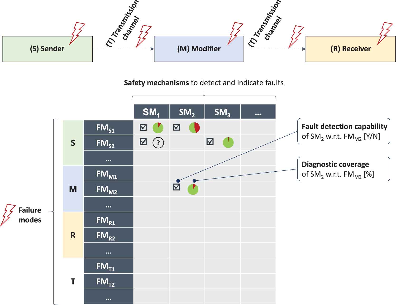
Approach to evaluate and select safety mechanisms.
As ISO 26262 only provides high level guidance on component faults and a fault model for generic data transmission, one of the first steps in the project was to develop/refine a fault model for video systems. The authors systematically identified and analyzed potential FMs of each component type [3,21]. As an example, for receiver components realized by displays, 30+ FMs were identified and analyzed. These failure modes FMRi include, e.g.,
Image corruption;
Image distortion;
Frozen image;
Delayed image;
Erroneous zoom factor;
Erroneous image orientation/color/contrast/brightness;
Image artifacts;
Erroneous augmentation/marking and
Modification/loss of essential image information [21].
In a systematic analysis of SMs for video systems, for each identified SM, the detectable FMs and the DC w.r.t. these FMs were documented (Figure 3, bottom). In a matrix with the FMs as rows and the SMs as columns, the capability of a safety mechanism SMx to detect failure mode FMy was indicated by a checkmark in the corresponding cell. If known, the DC, i.e. the percentage of the detectable faults, was being captured as well.
Such an analysis can be used to devise suitable and efficient SMs for a video system under development:
If, e.g., FMS1 and FMM2 need to be detected with medium DC (i.e., ≥ 90%) each, a combination of SM1 and SM2 could be implemented. SM2 alone would not suffice, as it would only be capable to detect FMM2 with the required medium DC, but not FMS1. FMS1 could be detected by SM2 as well, but only with low (i.e., ≥60%) and thus insufficient DC. Therefore, SM1 needs to be implemented as well.
Should the detection of FMR1 be required as well, none of the listed SMs would be suitable. In such a case, an additional (usually system-specific) SM needs to be devised.
This way, gaps w.r.t. detecting certain FMs were identified and informed the development of new and enhanced SMs within the project.
4.3. Proposed SMs
To address the identified gaps regarding the available SMs for video systems, multiple SMs were enhanced and new ones were proposed (see, e.g., [4,18,21]). As an example, this paper outlines “enhanced display monitoring,” a software-based SM that targets failures occurring in the receiver components (see [4] for details).
4.3.1. Enhanced display monitoring
Detecting a variety of issues related to the incorrect reproduction of images in the display was identified as a weakness of the available SMs.
One approach to facilitate the correct image reproduction by the display is monitoring the optical emission of the display using photo diodes located next to the display (cf. Figure 7). The data measured by the photo diodes is being compared with results from a model (target data obtained by reference images) or image processing methods (camera).
The fault detection capability of this approach increases with the number of photo diodes used. As placing one photo diode next to each subpixel of the display is not feasible in an experimental setting and might be cost-prohibitive even for specialized mass production displays, the authors evaluated variants using much fewer photo diodes. An evaluation of the capabilities of this approach can be found in Section 6.
A second approach to detect erroneous image reproduction exploits the fact that the supply current of the column drivers of an OLED or LCD display depends on the intensity of the color components of the pixels to be displayed. This correlation can be utilized when comparing the actual, measured current of a column driver with the expected current calculated based on the intensity information of the pixels to be displayed (monitoring the current of the column drivers). The expected current stems from a model derived from test patterns.
Neither monitoring the optical emission of the display using a limited number of photo diodes nor monitoring the current of the column drivers alone allows to judge the correctness of the image data at the pixel level. However, combining these two approaches could significantly improve fault detection capabilities.
4.4. Library of SMs
This combination of monitoring the optical emission of the display and monitoring the current of the column drivers discussed in 0 is an example for an envisioned bundling of individual SMs into larger building blocks. When designing future safety-related video systems, safety engineers would pick from these building blocks rather than combining individual SMs.
5. PROPOSED SAFETY ARCHITECTURE
In addition to designing and implementing a library of SMs for the detection and indication of component faults/failures, further SMs are needed to control the identified faults, to warn the driver, or to transition the system into a safe state.
Also, the fault and status information calculated by the distributed SMs of the individual system components needs to be collected and orchestrated at the system level.
To standardize the implementation of SMs for video systems, the authors propose the generic safety architecture depicted in Figure 4. As per this architecture, the conceptual model (see Figure 2) is being extended by an additional component type, the so-called ASIL-prepared video safety system (APVSS).
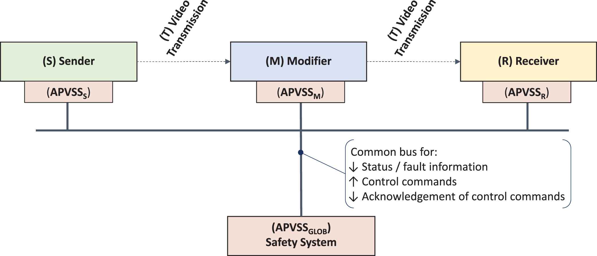
Generic safety architecture for video data transmission and processing systems.
The individual video system components are connected via a common APV bus, e.g., a dedicated CAN bus or an ethernet connection (Figure 4). This APV bus is different from the transmission channels (video links) used to transmit the actual pixel data.
The local SMs of the individual S, M, and R components collect status and/or fault information and broadcast it via the APV bus to a global APV Safety System (APVSSGLOB) component (Figure 4).
The global APVSS collects the status/fault information received via the APV bus and aggregates it. Aggregation and processing of this information within the APVSS takes place in two stages: (1) health monitoring for individual components and (2) system wide health monitoring (Figure 5). Based on the aggregated system health status, counter measures are derived and communicated as control commands via the APVSS bus to selected components (Figure 4).

Algorithmic structure of the safety system.
The components which received control commands acknowledge this information. The acknowledgement of control commands is also being processed by the APVSS (Figure 4).
To facilitate reuse, the information exchange from/to the APVSS has to be based on standardized messages. As an example, all status/fault information messages would utilize the following structure:
Sender ID;
Receiver IDs;
Parameter ID;
Parameter Value;
Parameter Quality;
Parameter ASIL capability.
The APV bus is considered to be a gray channel. Therefore, the messages communicated via this bus need to be protected against communication errors2 and may need to be time-stamped.
Assuming this standardized message structure, the authors were able to estimate the utilization of the APV bus by the individual SMs.
It is not necessary to implement the APVSS as a separated, single component. Alternatively, it can be implemented as part of one of the existing components or it can be distributed across multiple system components (e.g., S and R). This way, the communication resources needed to realize the APVSS could be optimized. A hybrid APVSS, consisting of local APVSS components that aggregate local information and a global APVSS that conducts the system-level aggregation, seems to be a promising architecture.
It might also be necessary to implement local data exchange between S, T, M, and R to implement system- level SMs that require multiple components to collaborate (e.g., a communication channel between S and R to achieve a synchronized timing).
The proposed safety architecture can be used to protect a single channel fail-safe or fail-silent video data transmission/processing system. However, an APVSS can also be used to monitor and control dual-channel fail-operational systems.
6. PROOF OF CONCEPT
6.1. Demonstrator Setup
Aa a proof of concept, a demonstrator representing an automotive video system consisting of a camera, a modifier, a display unit, video links to connect them as well as an APVSS was built (Figure 6). The demonstrator was used to devise, prototype, and evaluate SMs to detect and indicate component faults [4] and to prototype the system-level safety architecture and SMs to react on component status and FMs.
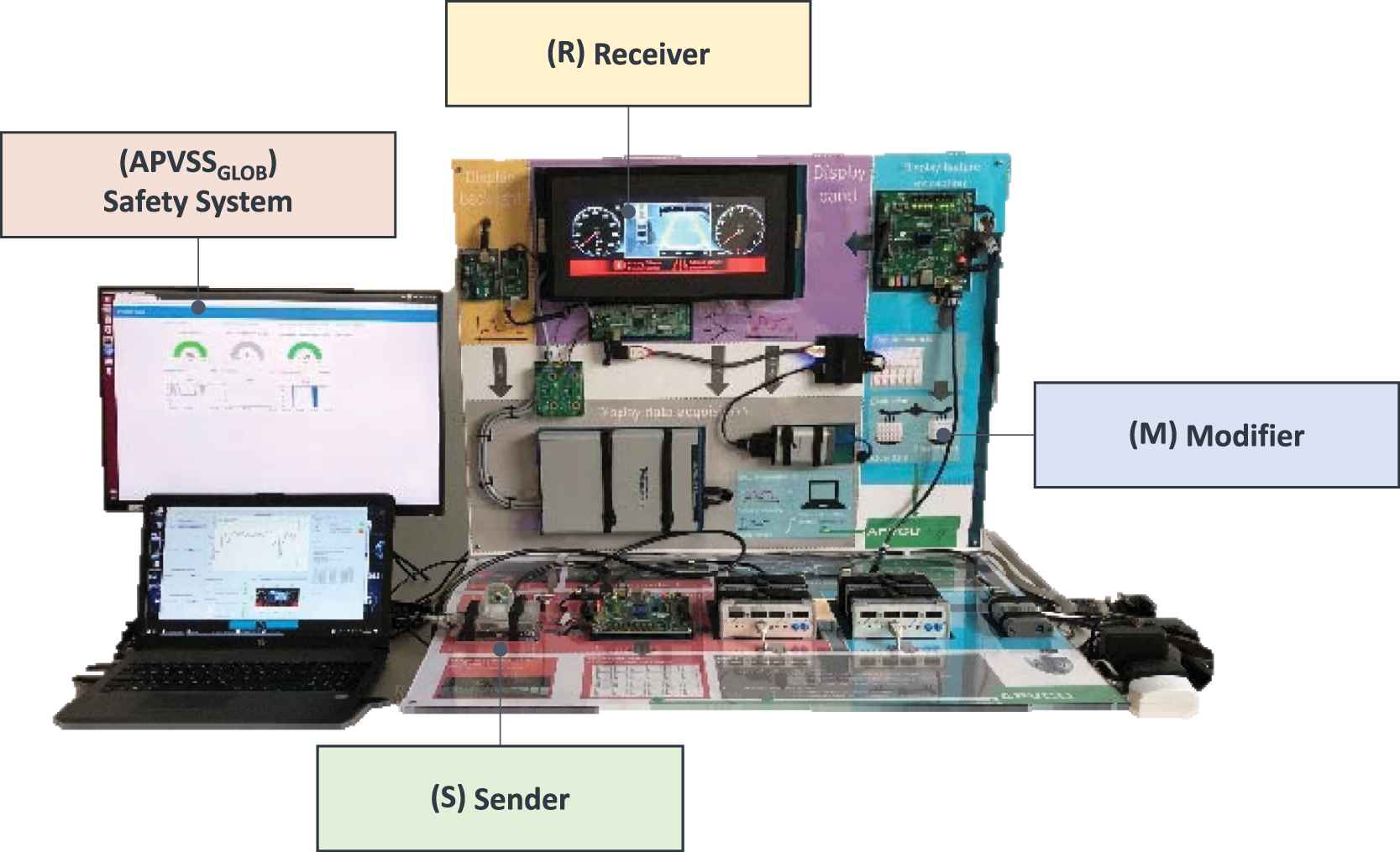
Proof of concept demonstrator.
Among other things, the demonstrator was used to validate the novel and enhanced SMs outlined in Section 4.3. As an example, the display unit of the demonstrator was diagnosed by enhanced display monitoring, namely by “monitoring of the current of the columns drivers” and “monitoring the optical emission of the display” using photo diodes (see Section 4.3.1 and [4] for further details).
All SMs generated status and fault information that was transmitted to the global APVSS component. Based on the fault/status information from the system components the APVSS was able to identify and report different faults. Fault detection capabilities and DC could be examined based on fault injection mechanisms.
Envisioned enhancements include the implementation of SMs to react to the detected faults and failures, e.g., by transitioning the system into a safe state.
6.2. Refinement of SMs
Usually, different types of information are displayed at fixed positions or in fixed areas of the display. This property can be used to divide the image to be displayed into regions of interest (ROIs) and apply dedicated and optimized SMs to the individual ROIs rather than the entire image.
An example is the display content shown in the top row of Figure 7 that could be divided into three ROIs. An analogue style (clockface) speedometer is displayed as a digital image in the left ROI. For this ROI, the sender component would not be a camera but a digital image processor.
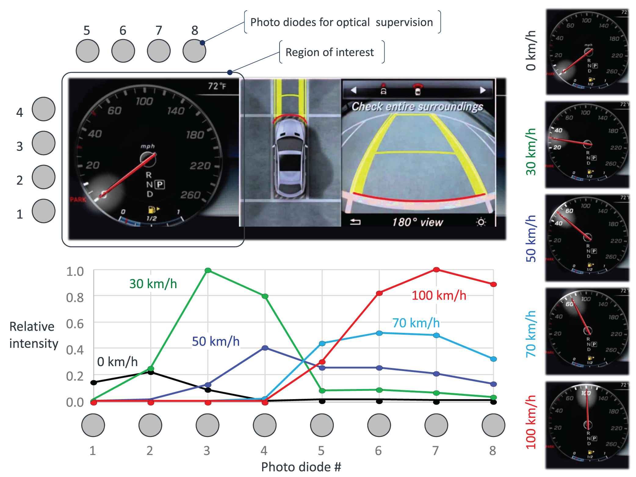
Monitoring the optical emission of the display using photo diodes for a speedometer.
Displaying an analogue-style speedometer is an example of a specific, but recurring use case. Generic SMs for fault detection can be refined or adapted to enhance their fault detection capabilities.
As an example, we refined the generic SM “monitoring the optical emission of the display” using photo diodes (see Section 4.3.1) for the speedometer use case as follows:
Eight photo diodes were arranged next to the ROI reproducing the speedometer display as shown in the top left part of Figure 7. To achieve significant differences of the intensities of the optical emissions measured by those photo diodes for different vehicle speeds, an optimized visualization of the actual speed using a torch effect around the tip of the indicator needle was used. Figure 7, right shows the expected images for 0, 30, 50, 70, and 100 km/h respectively.3 Similar visualizations are already in use to facilitate better usability of the speedometer and a higher perceived value of the automotive HMI.
The eight photo diodes measure the intensity of the light emission of the display through the cover glass. Bright pixels near a photo diode result in a higher intensity output than distant or dark ones. Figure 7 bottom row shows the measured intensities of the 8 photo diodes for 0, 30, 50, 70, and 100 km/h respectively. It is easy to see that each of these speeds can be identified by comparison of the relative intensities. For example, 30 km/h results in a high intensity of the photo diodes #3 and #4 because the “torch light” is closest by. The maximum intensities for 50 and 70 km/h are lower as the lit area is further away.
This refined SM facilitates a relatively cheap supervision of the actual optical display output such that the displayed speed can be verified with an accuracy of approx. 5 km/h for speeds from 0 to 100 km/h. For speeds beyond 100 km/h the accuracy drops to 10 km/h.4
This refined SM is definitively a significant progress to current implementations without optical supervision of the display output.
7. SUMMARY AND CONCLUSION
Based on a method for systematic gap analysis of existing SMs for fault detection in automotive video data transmission and processing systems, the authors devised
Enhanced and novel SMs to identify and indicate critical faults in such systems and their components.
A generic safety architecture for such systems that provides a framework to process fault and status information from SMs distributed across the system in a uniform way.
Both, the SMs and the safety architecture can be used to improve the functional safety of current and future automotive video data transmission and processing systems:
The devised SMs provide increased fault detection for FMs not sufficiently covered by the existing mechanisms.
The safety architecture allows to realize a standardized, uniform safety concept in a wide range of video systems. It facilitates the integration of legacy components as well as future cameras, modifiers, and display units from different suppliers. It provides a path to address the high number of variants expected in future automotive video systems.
A proof of concept for the proposed SMs and the safety architecture was established using a demonstrator.
The authors plan to utilize the demonstrator to further refine the SMs and APVSS algorithms as well as to investigate enhancements such as service discovery.
Future work also includes to bundle SMs into common building blocks to simplify the selection of suitable SMs for upcoming video data transmission and processing systems.
The safety architecture can be used as a foundation to derive a detailed specification for the functional safety aspects of video system components that can be realized by different suppliers.
Down the road, the authors envision that the APVSS component as well as other video system components can be developed as safety elements out of context (SEooCs) according to ISO 26262.
Footnotes
This definition goes beyond the scope of ISO 16505 [2] which defines a CMS as an ‘entity used in vehicles that presents the required outside information of a specific field of view to the driver of the vehicle, replacing conventional mirror system by means of electronic image capture and display devices’.
Common SMs to protect bus communication such es End2End protection, enable the receiver to detect faults / failures of the communication channel, but cannot prevent these faults / failures.
These speed values were chosen as being representative for speed limits in many countries.
Using the arrangement of photo diodes shown in Figure 7, speeds up to 140 km/h could be verified. For higher speeds, the torch light visualization is beyond the practical range of photo diode #8. However, a different speedometer design and/or a different arrangement of photo diodes could enable the verification of higher speeds as well.
REFERENCES
Cite this article
TY  - JOUR
AU  - Mirko Conrad
AU  - Frank Langner
AU  - Benjamin Axmann
AU  - Karlheinz Blankenbach
AU  - Jan Bauer
AU  - Matthäus Vogelmann
AU  - Manfred Wittmeir
AU  - Sascha Xu
PY  - 2021
DA  - 2021/02/22
TI  - Improving Functional Safety of Automotive Video Data Transmission and Processing Systems
JO  - Journal of Automotive Software Engineering
SP  - 15
EP  - 26
VL  - 2
IS  - 1
SN  - 2589-2258
UR  - https://doi.org/10.2991/jase.d.210213.001
DO  - 10.2991/jase.d.210213.001
ID  - Conrad2021
ER  -