
A Standard Driven Software Architecture for Fully Autonomous Vehicles
- DOI
- 10.2991/jase.d.200212.001How to use a DOI?
- Keywords
- Intelligent vehicles; Autonomous vehicles; Robotics; Software architecture
- Abstract
The development of self-driving vehicles is often regarded as adding a layer of intelligence on top of classic vehicle platforms. However, the amount of software needed to reach autonomy will exceed the software deployed for operation of normal vehicles. As complexity increases, the demand for proper structure also increases. Moreover, the shift from open, deterministic components to more opaque, probabilistic software components raises new challenges for system designers. In this paper we introduce a functional software architecture for fully autonomous vehicles aimed to standardise and ease the development process. Existing literature presents past experiments with autonomous driving or implementations specific to limited domains (e.g. winning a competition). The architectural solutions are often an after-math of building or evolving an autonomous vehicle and not the result of a clear software development life-cycle. A major issue of this approach is that requirements cannot be traced with respect to functional components and several components group most functionality. Therefore, it is often difficult to adopt the proposals. In this paper we take a prescriptive approach starting with requirements from a widely adopted automotive standard. We follow a clear software engineering process, specific to the automotive industry. During the design process, we make extensive use of robotic architectures – which seem to be often ignored by automotive software engineers – to support standard driven requirements.
- Copyright
- © 2020 The Authors. Published by Atlantis Press SARL.
- Open Access
- This is an open access article distributed under the CC BY-NC 4.0 license (http://creativecommons.org/licenses/by-nc/4.0/).
1. INTRODUCTION
Autonomous driving is no longer a lab experiment. As manufacturers compete to raise the level of vehicle automation, cars become highly complex systems. Driving task automation is often regarded as adding a layer of cognitive intelligence on top of basic vehicle platforms [1]. While traditional mechanical components become a commodity [2] and planning algorithms become responsible for critical decisions, software emerges as the lead innovation driver. Recent trends forecast an increase in traffic safety and efficiency by minimising human involvement and error. The transfer of total control from humans to machines is classified by the Society of Automotive Engineers (SAE) as a stepwise process on a scale from 0 to 5, where 0 involves no automation and 5 means full-time performance by an automated driving system of all driving aspects, under all roadway and environmental conditions [3]. Since the amount of software grows, there is a need to use advanced software engineering methods and tools to handle its complexity, size and criticality. Software systems are difficult to understand because of their non-linear nature – a one bit error can bring an entire system down, or a much larger error may do nothing. Moreover, many errors come from design flaws or requirements (mis-) specifications [4].
Basic vehicles already run large amounts of software with tight constraints concerning real-time processing, failure rate, maintainability and safety. In order to avoid design flaws or an unbalanced representation of requirements in the final product, the software's evolution towards autonomy must be well managed. Since adding cognitive intelligence to vehicles leads to new software components deployed on existing platforms, a clear mapping between functional goals and software components is needed.
Software architecture was introduced as a means to manage complexity in software systems and help assess functional and non-functional attributes, before the build phase. A good architecture is known to help ensure that a system satisfies key requirements in areas such as functional suitability, performance, reliability or interoperability [5].
The goal of this paper is to design a functional software architecture for fully autonomous vehicles. Existing literature takes a descriptive approach and presents past experiments with autonomous driving or implementations specific to limited domains (e.g. winning a competition). The architectural solutions are therefore an after-math of building or evolving an autonomous vehicle and not the result of a clear software development life-cycle. A major issue of this approach is that requirements cannot be traced with respect to functional components and several components group most functionality. Therefore, without inside knowledge, it is often not straight forward to adopt the proposals.
In this paper we take a prescriptive approach driven by standard requirements. We use requirements from the SAE J3016 standard, which defines multiple levels of driving automation and includes functional definitions for each level. The goal of SAE J3016 is to provide a complete taxonomy for driving automation features and the underlying principles used to evolve from none to full driving automation. At the moment of writing this paper, it is the only standard recommended practice for building autonomous vehicles. We provide an extensive discussion on the design decisions in the form of trade-off analysis, which naturally leads to a body of easily accessible distilled knowledge. The current proposal is an extension of our prior work [6].
The term functional architecture is used analogous to the term functional concept described in the ISO 26262 automotive standard [1,7]: a specification of intended functions and necessary interactions in order to achieve desired behaviours. Moreover, it is equivalent to functional views in software architecture descriptions; which provide the architects with the possibility to cluster functions and distribute them to the right teams to develop and to reason about them [4]. Functional architecture design corresponds to the second step in the V-model [7,8], a software development life cycle imposed by the mandatory compliance to ISO 26262 automotive standard.
We follow the methodology described by Wieringa [9] as the design cycle; a subset of the engineering cycle which precedes the solution implementation and implementation evaluation. The design cycle includes designing and validating a solution for given requirements.
The rest of the paper is organised as follows. In Section 2 we introduce background information. In Section 3 we infer the requirements from the SAE J3016 standard. In Section 4 we present the reasoning process that lead to a solution domain. The functional components are introduced in Section 5, followed by component interaction patterns in Section 6 and a general trade-off analysis in Section 7. A discussion follows in Section 8. In Section 9 we compare the proposal with related work and conclude with future research in Section 10.
2. BACKGROUND
The development of automotive systems is distributed between vehicle manufacturers, called Original Equipment Manufacturers (OEM), and various component suppliers – leading to a distributed software development life cycle where the OEM play the role of technology integrators. This development process allows OEM to delegate responsibility for development, standardisation and certification to their component suppliers. The same distributed paradigm preserves, at the moment, for component distribution and deployment inside a vehicle; where no central exists.
Instead, embedded systems called Electronic Control Units (ECU) are deployed on vehicles in order to enforce digital control of functional aspects such as steering or brakes. Many features require interactions and communications across several ECUs. For example, cruise control needs to command both the breaking and the steering system based on the presence of other traffic participants. In order to increase component reuse across systems, manufacturers and vendors developed a number of standardised communication buses (e.g. CAN, FlexRay) and software technology platforms (e.g. AUTOSAR) that ease communication and deployment between distributed components. We are hereby concerned with designing functional software components which are deployed on ECU and are required to exchange information over one or many communication buses. Standardised interfaces (such as the ones defined in AUTOSAR) help ease the development and communication between software components, however, they do not have a big impact on their core functionality.
As mentioned in Section 1, SAE J3016 is a standard that defines multiple levels of automation, sketching an incremental evolution from no automation to fully autonomous vehicles. The purpose of the standard is to be descriptive and broad about this evolution, but it does not provide strict requirements for it. However, at the moment, it is the most comprehensive, widely adopted, document that drives this evolution. Given its wide adoption, we use it as a baseline for our approach: vehicles should satisfy at least the functions described by this standard in order to qualify for automation levels. With the goal of understanding the vehicle automation process, we first introduce the most important terms as defined by SAE J3016 [3]:
Dynamic Driving Task (DDT) – real-time operational and tactical functions required to operate a vehicle, excluding strategic functions such as trip scheduling or route planning. DDT is analogous to driving a car on a predefined route and includes actuator control (e.g. steering or braking) and tactical planning such as generating and following a trajectory, keeping the vehicle within the lanes, maintaining distance from other vehicles, etc.
Driving automation system – hardware and software systems collectively capable of performing some parts or all of the DDT on a sustained basis. Driving automation systems are usually composed of design-specific functionality called features (e.g. automated parking, lane keep assistance, etc.). The interplay between hardware and software was described earlier. We are currently interested in the interplay between software components in order to design driving automation systems capable to achieve full autonomy.
Operational Design Domains (ODD) – the specific conditions under which a given driving automation system or feature is designed to function. Defining an operational domain is an important task during the design phase, as the requirements change in relation to it. For example, a vehicle which should operate in sunny weather in a limited area of a city has different requirements than a vehicle which should operate in winter conditions, on mountain roads. As will be discussed later, full autonomy requires a vehicle to operate without intervention in all weather and traffic conditions.
DDT fall-back – the response by the user or by an Automated Driving System (ADS) to either perform the DDT task or achieve a safety state after occurrence of a DDT performance-relevant system failure or upon leaving the designated ODD.
DDT fall-back-ready user – the user of a vehicle equipped with an engaged ADS feature who is able to operate the vehicle and is receptive to ADS-issued requests to intervene and to perform any if not all of the DDT tasks during a system failure or when an automated vehicle requests it.
DDT feature – a design-specific functionality at a specific level of driving automation with a particular ODD. A feature can be seen as a specific hardware or software component that is performs a driving automation task in a predefined domain. We may think of lane assistance in sunny weather as a DDT feature.
Besides hardware constraints, full vehicle automation involves the automation of the DDT in all ODD, by developing a driving automation system. Recursively, driving automation systems are composed of design-specific features. In this sense, complete vehicle automation is seen as developing, deploying and orchestrating enough DDT features in order to satisfy all conditions (ODDs) in which a human driver can operate a vehicle (safely).
The SAE classification of driving automation for on-road vehicles, showcased in Figure 1, is meant to clarify the role of a human driver, if any, during vehicle operation. The first discriminant condition is the environmental monitoring agent. In the case of no automation up to partial automation (levels 0-2), the environment is monitored by a human driver, while for higher degrees of automation (levels 3-5), the vehicle becomes responsible for environmental monitoring.
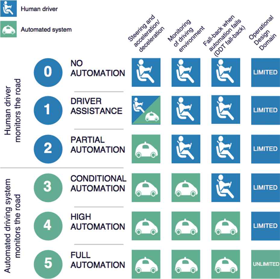
SAE J3016 levels of driving automation.
Another discriminant criteria is the responsibility for DDT fall-back mechanisms. Intelligent driving automation systems (levels 4-5) embed the responsibility for automation fall-back constrained or not by operational domains, while for low levels of automation (levels 0-3) a human driver is fully responsible.
According to SAE:
If the driving automation system performs the longitudinal and/or lateral vehicle control, while the driver is expected to complete the DDT, the division of roles corresponds to levels 1 and 2.
If the driving automation system performs the entire DDT, but a DDT fall-back ready user is expected to take over when a system failure occurs, then the division of roles corresponds to level 3.
If a driving automation system can perform the entire DDT and fall-back within a prescribed ODD or in all driver-manageable driving situation (unlimited ODD), then the division of roles corresponds to levels 4 and 5.
3. REQUIREMENTS INFERENCE
The process of functional architecture design starts by developing a list of functional components and their dependencies [4]. Towards this end, SAE J3016 defines three classes of components:
Operational – basic vehicle control,
Tactical – planning and execution for event or object avoidance and expedited route following and
Strategic – destination and general route planning.
Each class of components has an incremental role in a hierarchical control structure which starts from low level control, through the operational class and finishes with a high level overview through the strategic class of components. In between, the tactical components handle trajectory planning and response to traffic events. This hierarchical view upon increasing the level of vehicle automation is an important decision driver in architecture design.
Later, the SAE definition for DDT specifies, for each class, the functionality that must be automated in order to reach full autonomy (level 5):
Lateral vehicle motion control via steering (operational).
Longitudinal vehicle control via acceleration and deceleration (operational).
Monitoring of the driving environment via object and event detection, recognition, classification and response preparation (operational and tactical).
Object and event response execution (operational and tactical).
Manoeuvre planning (tactical).
Enhanced conspicuity via lighting, signalling and gesturing, etc. (tactical).
Moreover, a level 5 vehicle must ensure DDT fall-back and must implement strategic functions, not specified in the DDT definition. The latter consists of destination planning between two points provided by a human user or received from an operational centre.
An overview of the hierarchical class of components defined is illustrated in Figure 2. The level of complexity increases from left to right – from operational to strategic functions.
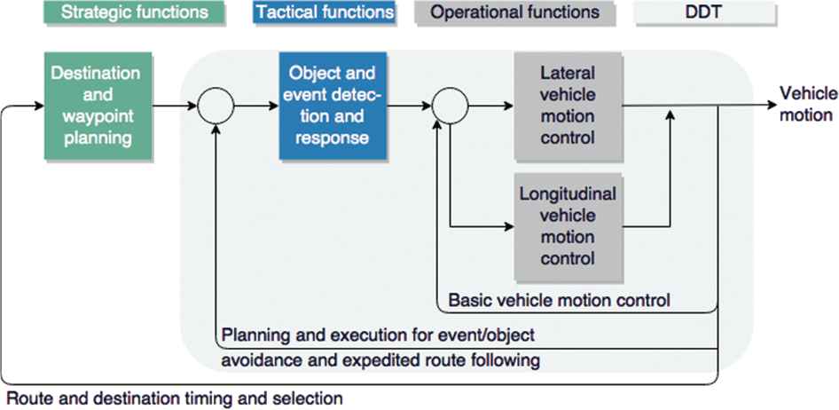
Functional component classification according to SAE J3016 [3].
Although not exhaustive, the list of components and their intended behaviour, as specified by SAE J3016, represents a good set of initial requirements. It is the choice of each OEM how any of the intended functionality will be implemented. For example, different algorithms or software systems could be used to implement object detection, recognition and classification. This choice can impact the final set of functional components because one OEM can choose to use multiple sensors and powerful sensor fusion algorithms, while other OEM can build a single component that can handle all tasks. In this paper, we strive to divide each function into atomic components. If any of these pieces will be combined in higher level components, it won't have any impact on this proposal. An in-depth analysis of such trade-offs, often driven by the distributed software development life-cycle, is presented in Section 7.
We briefly remind that the automation of any task is a control loop which receives input from sensors, performs some reasoning and acts upon the environment (possibly through actuators) [10]. The automation of complex tasks requires a deeper (semantic) understanding of sensor data in order to generate higher order decisions or plans. However, the loop behaviour is preserved. This analogy holds for the SAE classification of functional components illustrated in Figure 2. Each class of components can be implemented as a control loop which receives input from sensors and acts accordingly. From left to right – from operational to strategic functions – the level of semantic knowledge needed in order to make a decision increases. Moreover, as we move further from left to right, the components do not control actuators anymore, but other components. For example, tactical components will send commands to operational components. Similarly, strategic functions cannot directly act upon actuators, but communicate with tactical functions, which will later command operational functions.
Thus we can regard each class of components as a big loop – illustrated in Figure 2 – and each component in each class as a smaller loop because each component will require certain semantic information and not all the information available at class level. We will exploit this behaviour in the following section.
4. RATIONALE
Software architecture design for autonomous vehicles is analogous to the design of a real-time, intelligent, control system – or a robot. Although we can find considerably literature concerning software architecture in the field of robotics and artificial intelligence [11–17], these proposals seem to be overlooked by automotive software engineers. Therefore, many reference architectures for autonomous vehicles miss developments and trade-offs explored in the field of robotics – as we will shall see in Section 9. We aim to bridge this gap in this section, by discussing the most important developments in the field of robotics and select the best choices for the automotive domain.
For a long time, the dominant view in the AI community was that a control system for autonomous robots should be composed of three functional elements: a sensing system, a planning system and an execution system [18]. This view led to the ubiquitous sense-plan-act (SPA) paradigm. For planning, a system typically maintains an internal state representation, which allows it to position itself in the environment and plan next actions. Because this model has to be up-to-date and accurately reflect the environment in which a robot operates, it might require a lot of information. As the operational environment becomes more complex, the complexity of the internal representation also increases, increasing the time needed to plan the next steps. Therefore, in fast changing environments, new plans may be obsolete before they are deployed. Moreover, unexpected outcomes from the execution of a plan stem may cause the next plan steps to be executed in an appropriate context and lead to unexpected outcomes.
One question that naturally stood up from these shortcomings is “how important is the internal state modelling?” In order to answer this question, several definitions meant to achieve similar goals were proposed. Maes [11] first distinguishes between behaviour and knowledge based systems – where knowledge-based systems maintain an internal state of the environment, while behaviour-based systems do not [11]. Similarly, the literature distinguishes between deliberative and reactive systems, where deliberative systems reason upon an internal representation of the environment and reactive system fulfil goals through reflexive reactions to environment changes [13–16]. Reactive or behaviour based systems are able to react faster to a changing environment, but reason less about it.
We find both definitions to answer the same questions – “how will a system plan its decisions?” Through reasoning on complex semantic information extracted from its sensors or by simple reactions to simple inputs? Deciding on this is an initial trade-off between speed of computation and the amount of environmental understanding a system can have.
When considering the development of autonomous vehicles through these lenses, we can see that vehicles require both reactive and deliberative components. Maintaining a pre-defined trajectory and distance from the objects around a vehicle is an example of a reactive system, which should operate with high frequency and be as fast as possible in order to overcome any environmental change. In this case, maintaining a complex representation of the surrounding environment is futile.
However, a decision making mechanism responsible, for example, to overtake the vehicle in front is an example of a deliberative system. In this case maintaining a complex world model can help the system to take a better decision.
For example, one can not only judge the distances to the surrounding objects, but also the relevance of the decision in achieving the goal. Is it worth to overtake the car in front if the vehicle must turn right in a relatively short distance after the overtake? In order to answer this question a complex world model that must combine semantic information about the overall goal, future states and nearby objects is needed. Processing this amount of information will naturally take a longer time. However, since the result can only impact the passengers comfort (assuming that driving behind a slow car for a long time is un-comfortable) the system can assume this processing time.
Gat and Bonnasso [13] first debate the role of internal state and establish a balance between reactive and deliberative components inside a system. In their proposal, the functional components are classified based on their memory and knowledge about the internal state in: no knowledge, knowledge of the past, or knowledge of the future – thus resulting in three layers of functional components. However, their model does not specify how, or if, the knowledge can be shared between the layers. Moreover, it is not clear how and if any components incorporate knowledge about past, future and other static data.
A better proposal, that bridges the gap between reactive and deliberative components, is the NIST Real Time Control Systems (RCS) reference architecture introduced by Albus [12]. This architecture does not separate components based on memory, but builds a hierarchy based on semantical knowledge.
Thus, components lower in the hierarchy have limited semantic understanding and can generate inputs for higher components, deepening their semantic knowledge and understanding. Moreover, RCS has no temporal limitations for a component's knowledge. One can hold static or dynamic information about past, present or future. Although all components maintain a wold model, this can be as simple as reference values, to which the input must be compared.
We find this proposal a good fit for automotive requirements and for the functional classification presented in Section 3 because it allows a balanced representation of reactive and deliberative components and it allows hierarchical semantic processing – one of the requirements given by the classification of functional components proposed earlier. Further on, we introduce more details about it and illustrate it in Figure 3.
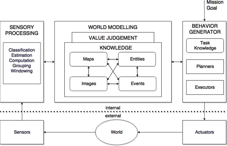
Real time intelligent control systems reference architecture [19].
At the heart of the control loop for an RCS node is a representation of the external world – the world model – which provides a site for data fusion, acts as a buffer between perception and behaviour, and supports both sensory processing and behaviour generation. Depending on the complexity of the task a node is responsible for, the complexity of the world model increases. For the simplest tasks, the world model can be very simple, such as in the case of a throttle system which only has knowledge about the velocity of the car and the inputs it receives from the acceleration pedal. For complex tasks, such as destination planning, the world model must include complex information such as the maps for an operational domain, real-time traffic information, etc.
Sensory processing performs the functions of windowing, grouping, computation, estimation and classification on input from sensors. World modelling can also maintain static knowledge in the form of images, maps, events or relationships between them. Value judgment provides criteria for decision making, while behaviour generation is responsible for planning and execution of behaviours [12].
Albus proposed the design for a node in a hierarchical control structure, where lower level nodes can generate inputs for higher level nodes, thus increasing the level of abstraction and cognition. Therefore, nodes lower in a hierarchy can have a very simplistic world model and behaviour generation functions and can easily implement reactive components. In order to keep in line with the example above, we consider the case of maintaining a distance from an object in front. A node implementing this functionality will only have to keep in the world model block the distance from the vehicle in front, the reference distance and the vehicle's velocity. The behaviour generation block will decide to issue a braking command whenever the distance will be too close or whenever it predicts (using the velocity of the vehicle) that the distance will decrease.
Higher nodes, representing deliberative components, can easily be described with the same architecture. Their world model block will process more semantic information and generate more complex behaviours (such as the decision to overtake the vehicle in front in order to increase the overall ride comfort and optimise the goal).
In this hierarchy, higher nodes consume semantic information extracted by lower nodes. However, this may not always the case with autonomous vehicles where several nodes, at different hierarchical levels, can consume the same information. For example, the distance from the vehicle in front can be used by both the reactive and the deliberative components introduced earlier. Moreover, several components at the same hierarchical layer can interact, as a sequential process.
From an architectural point of view, a sequential processing stream which follows different, individual, processing steps is represented through a pipes and filters pattern [20]. The pattern divides a process in several sequential steps, connected by the data flow – the output data of a step is the input to the subsequent step. Each processing step is implemented by a filter component [20].
In its pure form, the pipes and filters pattern can only represent sequential processes. For hierarchical structures, a variant of the pattern called tee and join pipeline systems is used [20]. In this paradigm, the input from sensors is passed either to a low level pipeline corresponding to a low level control loop, to a higher level pipeline or both.
An example is shown in Figure 4: the input from sensors is fed to different processing pipes. At a low level of abstraction, pipeline 1 only executes simple operations and sends the result to actuators.
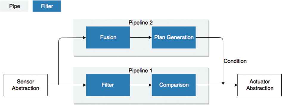
Tee and join pipelines architectural pattern.
At higher levels of abstraction, pipeline 2 processes more sensor data and generates manoeuvre plans which are translated to actuator language. A priority condition will decide which input to send to the actuators. Alternatives to this patterns will be further discussed in Sections 6 and 7. At the moment, we concentrate on the functional decomposition, which will suggest the nodes in the future architecture.
5. FUNCTIONAL DECOMPOSITION
We start by introducing the functional components and, in Section 6, discuss interaction patterns. Figure 5 depicts the functional components that satisfy SAE J3016 requirements for fully autonomous vehicles. The data flows from left to right; from the sensors abstraction to actuator interfaces, simulating a closed control loop. The figure represents three types of entities: functional components (blue boxes), classes of components (light grey boxes) and sub-classes of components (dark grey boxes).
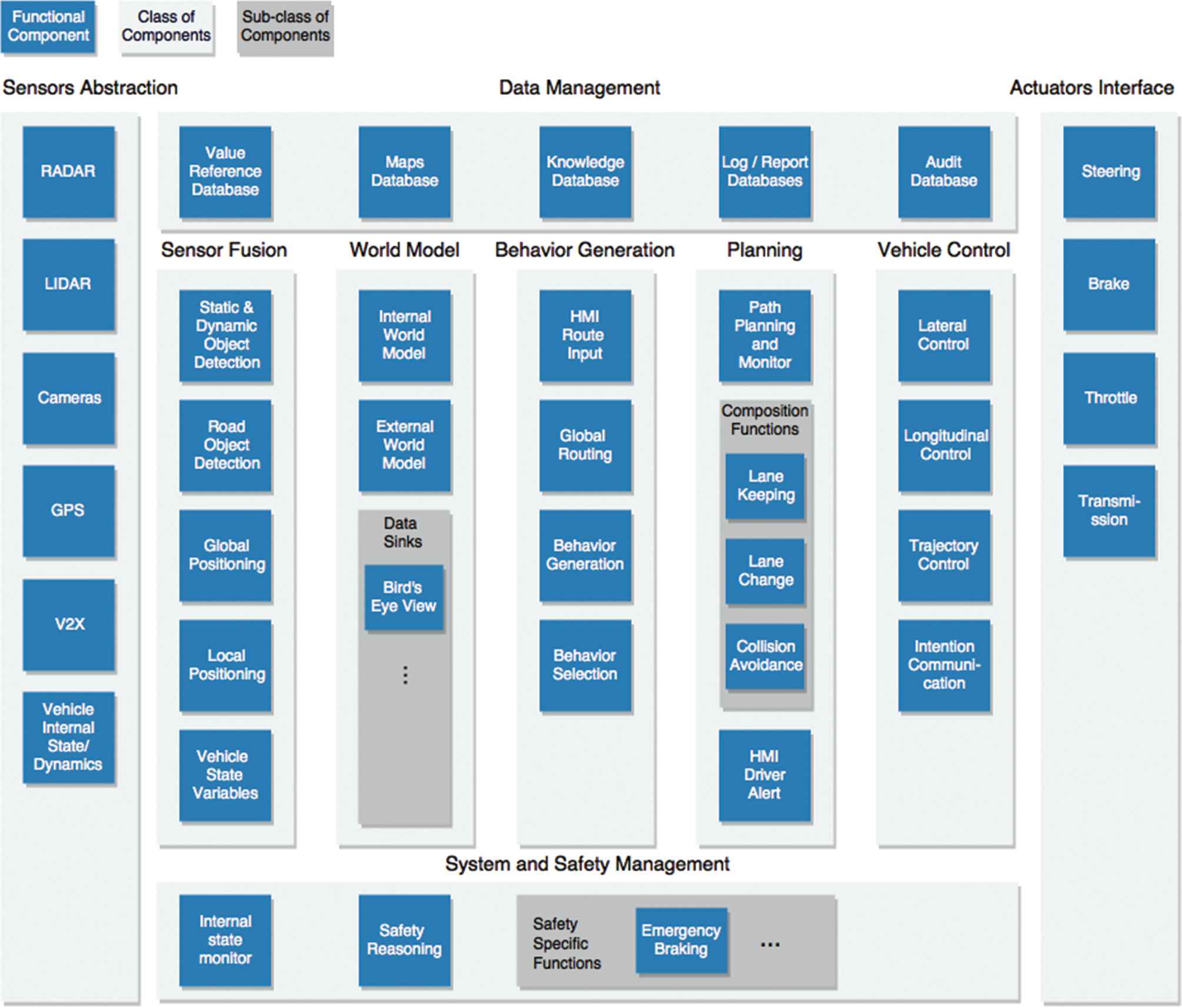
Proposed functional architecture, part I: functional components.
The proposal maps onto the SAE classification of functional components, introduced in Section 2, in the following way: vehicle control and actuators interface class of components correspond to SAE operational functions, the planning class of components corresponds to SAE tactical functions, and the behaviour generation class maps to both strategic and planning class of functions.
Two orthogonal classes, corresponding to data management and system and safety management, are depicted because they represent cross-cutting concerns: data management components implement long term data storage and retrieval, while system and safety management components act in parallel of normal control loops and represent DDT fall-back mechanisms or other safety concerns.
In the following subsections each class of filters is discussed together with its components. The last sub-section discusses the relation with middle-ware solutions and AUTOSAR.
5.1. Sensor Abstractions
Sensor abstractions provide software interfaces to hardware sensors, possible adapters and conversion functionality needed to interpret the data. We distinguish two classes of sensors and, respectively, of abstractions: (1) sensors that monitor the internal vehicle state or dynamic attributes (e.g. inertial measurements, speed, etc.) and (2) sensors that monitor the external environment as required by the SAE requirements.
Environmental monitoring can be based on RADAR, LIDAR and camera technologies. In the case of cooperative driving, communication with other traffic participants is realised through vehicle-to-everything (V2X). Global positioning (GPS) is required to localise the vehicle in a map environment or to generate global routes and is therefore represented as a separated functional component.
All abstractions concerning the internal vehicle state are grouped into one functional component, because the choice is specific to each OEM.
5.2. Sensor Fusion
Multi-sensor environments generate large volumes of data with different resolutions. These are often corrupted by a variety of noise and clutter conditions which continually change because of temporal changes in the environment. Sensor fusion combines data from different, heterogeneous, sources to increase accuracy of measurements.
The functional components are chosen with respect to SAE requirements for object and event detection, recognition and classification. We distinguish between static and dynamic objects (e.g. a barrier, pedestrians) and road objects (e.g. traffic lights) because they have different semantic meaning. Moreover, local positioning is needed to position the vehicle relative to the identified objects and GPS is needed for strategic functionality.
Through sensor fusion, a processing pipeline gathering information from various sensors such as RADAR and camera can be defined in order to classify an object, determine its speed, and add other properties to its description. The distinction mentioned earlier between the external environment and the internal state of a vehicle is preserved in Figure 5: the first four components process data related to the external environment, while the internal state is represented by the last functional component.
5.3. World Model
The world model represents the complete picture of the external environment as perceived by the vehicle, together with its internal state. Data coming from sensor fusion is used together with stored data (e.g. maps) in order to create a complete representation of the world.
As in RCS architecture, the world model acts as a buffer between sensor processing and behaviour generation. Components in this class maintain knowledge about images, maps, entities and events, but also relationships between them. World modelling stores and uses historical information (from past processing loops) and provides interfaces to query and filter its content for other components. These interfaces, called data sinks, filter content or group data for different consumers in order to reveal different insights. One example heavily used in the automotive industry is the bird's eye view. However, the deployed data sinks remain OEM-specific.
5.4. Behaviour Generation
Behaviour generation is the highest cognitive class of functions in the architecture. Here, the system generates predictions about the environment and the vehicle's behaviour. According to the vehicle's goals, it develops multiple behaviour options (through behaviour generation) and selects the best one (behaviour selection). Often, the vehicle's behaviour is analogously to a Finite State Machine (FSM) or a Markov Decision Process (MDP). The behaviour generation module develops a number of possible state sequences from the current state and the behaviour reasoning module selects the best alternative. Complex algorithms from Reinforcement Learning (RL) use driving policies stored in the knowledge database to reason and generate a sequence of future states. Nevertheless, the functional loop is consistent: at first a number of alternative behaviours are generated, then one is selected using an objective function (or policy).
A vehicle's goal is to reach a given destination without any incident. When the destination changes (through a Human Machine Interaction (HMI) input), the global routing component will change the goal and trigger new behaviour generation. These components correspond to the SAE strategic functions.
5.5. Planning
The planning class determines each manoeuvre an autonomous vehicle must execute in order to satisfy a chosen behaviour. The path planning and monitoring component generates an obstacle free trajectory and composes the trajectory implementation plan from composition functions deployed on the vehicle. It acts like a supervisor which decomposes tasks, chooses alternative methods for achieving them, and monitors the execution. The need to re-use components across vehicles or outsource the development leads the path to compositional functions. These functions can be thought as DDT features, described in Section 2. Examples of such functions are: lane keeping systems or automated parking systems (all, commercial of-the-shelf deployed products).
Compositional functions represent an instantiation of the RCS architecture; they receive data input from sensor fusion or world modelling through data sinks, judge its value and act accordingly, sending the outputs to vehicle control. Path planning and monitoring acts as an orchestrator which decide which functions are needed to complete the trajectory and coordinate them until the goal is fulfilled or a new objective arrives. For vehicles up and including level 4, which cannot satisfy full autonomous driving in all driving conditions, the control of the vehicle must be handed to a trained driver in case a goal cannot be fulfilled. Therefore, this class includes a driving alert HMI component.
5.6. Vehicle Control
Vehicle control is essential for guiding a car along the planned trajectory. The general control task is divided into lateral and longitudinal control, reflecting the SAE requirements for operational functions. This allows the control system to independently deal with vehicle characteristics (such as maximum allowable tire forces, maximum steering angles, etc.) and with safety-comfort trade-off analysis. The trajectory control block takes a trajectory (generated at the path planning and monitoring level) as input and controls the lateral and longitudinal modules. The trajectory represents a future desired state given by one of the path planning compositional functions. For example, if a lane-change is needed, the trajectory will represent the desired position in terms of coordinates and orientation, without any information about how the acceleration, steering or braking will be performed. The longitudinal control algorithm receives the target longitudinal state (such as brake until 40 km/h) and decides if the action will be performed by accelerating, braking, reducing throttle or using the transmission module (i.e. engine braking). The lateral control algorithm computes the target steering angle given the dynamic properties of a vehicle and the target trajectory. If the trajectory includes a change that requires signalling, the communication mechanisms will be triggered through the intention communication module.
5.7. Actuator Interfaces
The actuator interface modules transform data coming from vehicle control layer to actuator commands. The blocks in Figure 5 represent the basic interfaces for longitudinal and lateral control.
5.8. Data Management
Data will at the centre of autonomous vehicles [21]. In spite of the fact that most data requires real-time processing, persistence is also needed. These concerns are represented using the data management class of components. Global localisation features require internal maps storage; intelligent decision and pattern recognition algorithms require trained models (knowledge database); internal state reporting requires advanced logging mechanisms (logging database). The logging-report databases are also used to store data needed to later tune and improve intelligent algorithms. Moreover, an audit database keeps authoritative logs (similar to black boxes in planes) that can be used to solve liability issues. In order to allow dynamic deployable configurations and any change in reference variables (e.g. a calibration or a decisional variable) a value reference database is included.
5.9. System and Safety Management
The system and safety management block handles functional safety mechanisms (fault detection and management) and traffic safety concerns. It is an instantiation of the separated safety pattern [22] where the division criteria split the control system from the safety operations. Figure 5 only depicts components that spot malfunctions and trigger safety behaviour (internal state monitor, equivalent to a watch dog), but not redundancy mechanisms. The latter implement partial or full replication of functional components. Moreover, safety specific functions deployed by the OEM to increase traffic safety are distinctly represented. At this moment they are an independent choice of each OEM.
As the level of automation increases, it is necessary to take complex safety decisions. Starting with level 3, the vehicle becomes fully responsible for traffic safety. Therefore, algorithms capable of full safety reasoning and casualty minimisation are expected to be deployed. While it is not yet clear how safety reasoning will be standardised and implemented in future vehicles, such components will soon be mandatory [23]. An overview of future safety challenges autonomous vehicles face is illustrated in [24]. With respect to the separated safety pattern, in Figure 5 safety reasoning components are separated from behaviour generation.
5.10. AUTOSAR Context
AUTOSAR is a consortium between OEM and component suppliers which supports standardisation of the software infrastructure needed to integrate and run automotive software. This paper does not advocate for or against AUTOSAR. The adoption and use of this standard is the choice of each OEM. However, due to its popularity, we consider mandatory to position the work in the standard's context. Given AUTOSAR, the functional components in Figure 5 represent AUTOSAR software components. The interfaces between components can be specified through AUTOSAR's standardised interface definitions. At the moment, the level of abstraction presented in this paper does not include software interface.
6. INTERACTIONS BETWEEN COMPONENTS
As mentioned in Section 4, the components in Figure 5 act as a hierarchical control structure, where the level of abstraction and cognition increases with the hierarchical level, mapping on the SAE classification of functional components. Components lower in the hierarchy handle less complex tasks such as operational functions, while higher components handle planning and strategic objectives (e.g. global routing or trajectory planning).
We propose the use of pipe-and-filter pattern for component interactions in flat control structures (same hierarchical level) and the use of tee-and-join pipelines to represent the hierarchy. In a hierarchical design, lower level components offer services to adjacent upper level components. However, the data inputs are often the same. A high level representation of the system, through the tee-and-join pipelines pattern is illustrated in Figure 6. The grey boxes represent processing pipelines and the blue ones represent components classes.
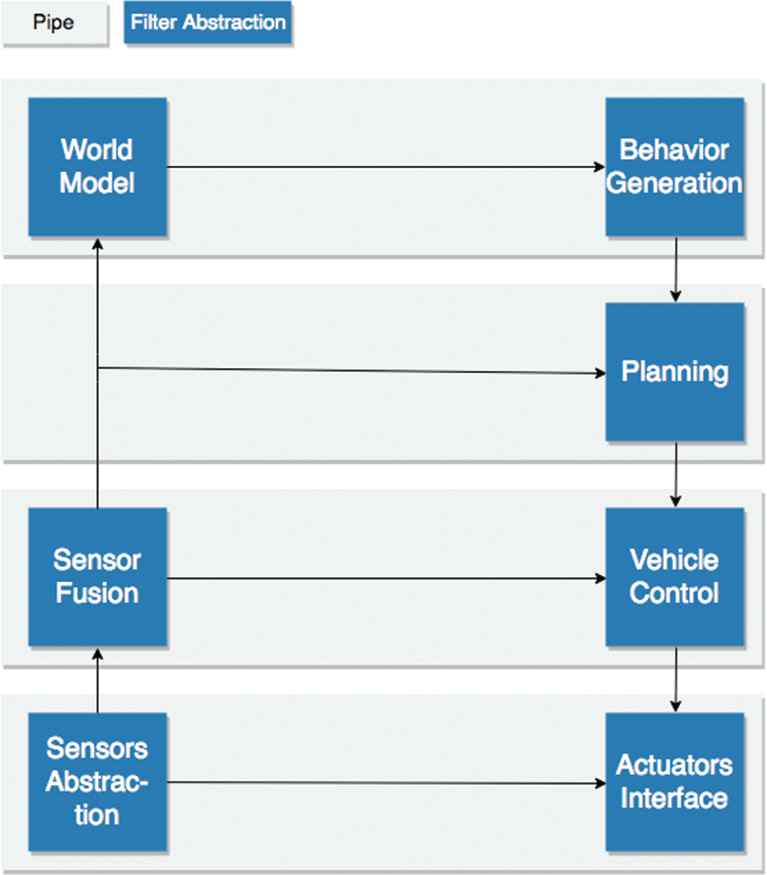
Proposed functional architecture, part II: hierarchical control structure using tee-and-join pipelines pattern.
For each component class, a process is analogous to a pipeline. As example, once a user communicates a final destination, the behaviour generation process starts. This example is illustrated in Figure 7, where upon receiving a destination at the HMI input filter, the global routing filter forwards a route to the behaviour generation filter. This filter breaks down the route in actions that have to be taken by the vehicle in order to reach the destination. The actions are analogous to states in a FSM. Often, there are several paths between two states. Further on, the behaviour selection component will select the best path between two states and forward it to the planning process.
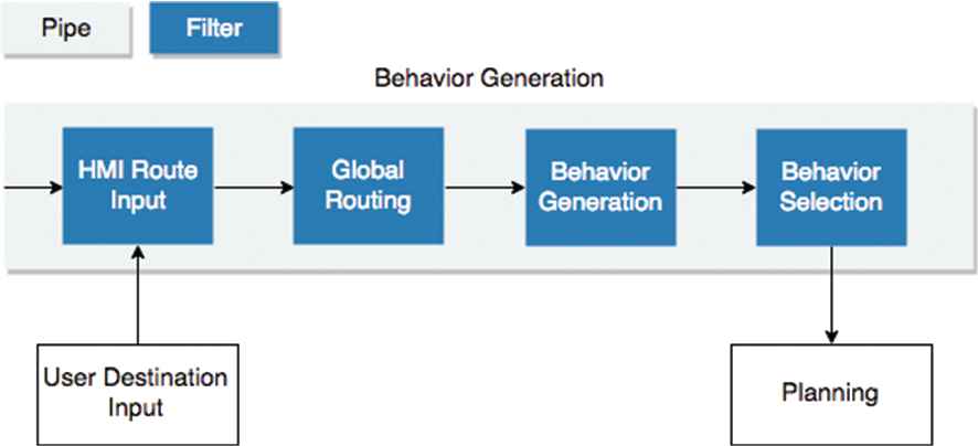
Proposed functional architecture, part III: component interaction at class level. The behaviour generation process.
Moreover, messages received at component level have to be prioritised. For example, an actuator interface can receive commands from the longitudinal control component or a safety specific function (e.g. emergency braking). In order to decide which command to execute first, the messages must contain a priority flag. Since this functionality is dependent on the component's interface and specific to OEM, this discussion is limited.
Various alternatives to the chosen interaction patterns will be discussed in the next section.
7. TRADE-OFF ANALYSIS
Software architecture design is often not deterministic. Given a set of requirements, different architects might come to different results. The process of weighting alternatives and selecting the most appropriate decisions is called trade-off analysis. Several decisions in this paper could be taken differently. Therefore, in this section we present several alternatives to our decisions and weight their advantages and disadvantages.
We will start from the underlying assumption of this paper – that we can derive a set of valid requirements from the SAE J3016 automotive standard. As mentioned in Section 2, the purpose of this standard is not to provide a complete definition of autonomy, but rather a minimal illustration of the functions needed in order to achieve it. It is meant to guide the process, and not exhaustively describe it. However, we find this information sufficient for our goals, because any functionality on top of the minimal requirements remains the choice of each OEM.
The second decision to be questioned is the use of NIST RCS architecture as a reference architecture for our work. An in-depth comparison with other works was presented in Section 4, however, we hereby present the trade-offs that come with choosing this reference architecture. Although it has the power to clearly discriminate between reactive and deductive components and is general enough to represent both types of components, this reference architecture can be sometimes too complex for simple nodes.
In order to properly represent simple functions, from the operational class, one does not need a complex world model or behaviour generator modules. In some components they might miss altogether. However, the architecture does not impose any constraints on the complexity of the world model. Thus, with limited world modelling or behaviour generation module the architecture can easily represent very simple control loops such as value comparators. Moreover, when compared to other proposals, this reference model allows each individual nodes to have a level of reasoning – while in other only components higher in a hierarchy are responsible for planning. This comes as a benefit for the automotive software development life-cycle and for the compositional functions we represented in the architecture.
We expect OEM to maintain their status of technology integrators and outsource more complex functionality to their suppliers – such as complete lane keeping or collision avoidance systems. These systems can easily be implemented as RCS nodes and integrated in the overall architecture.
We find the RCS model broad enough to allow the development of complex functionality, but sometimes too complex for simple functions – a trade-off that can be easily overcome by simplifying each block of the architecture in the latter case. A more expressive alternative would be to propose RCS nodes of different complexity – with lower level nodes that can replace world modelling only with value judgement. This decision must be weighted independently, as it might add clutter and other trade-offs when deciding which type of node should one choose for each component.
A third trade-off clearly regards the functional decomposition. Although we aim to atomically decompose every function and represent each sub-component individually, there is no way to prove this is the correct way. New market trends foresee the adoption of system-on-a-chip circuits that integrate more and more components. Technologies such as MobilEye [25] aim to group several functions on a dedicated chip. In such scenarios, sensor abstractions and fusion layers could be merged. However, the functions implemented by such circuits will still resemble our proposal. For example, even though the sensor abstraction layer compresses to one component, all the functionality at the sensor fusion layer still have to be implemented because static, dynamic or road objects detection is absolutely mandatory for autonomous driving. Therefore, our atomic decomposition is able to represent these evolutions.
A fourth trade-off to be considered concerns the choice for component interaction patterns. Several alternatives to the tee and join pipelines pattern have been considered. One clear alternative is to use a layered architecture – where the functional components are grouped in a hierarchy and function calls can be made from higher layers to lower ones [4]. However, this choice will constrain the possible interactions between components, thus limiting the design. At first, because each layer will encapsulate some components, it will be impossible to re-use or re-orchestrate them in other processes. Secondly, because the function calls at lower layers are required to come from upper layers, thus limiting even more the design.
Another alternative is to use a component based architecture, where all the components rest at the same hierarchical layer and any component can communicate with all others. This pattern seems a better fit for the automotive domain, where different components are deployed on various ECU and they communicate through a bus. However, it is unable to represent hierarchical reasoning.
We argue that the tee and join pattern is equivalent to the component based architecture, but has the ability to represent hierarchical processes. This is because from a component, one can easily begin a new pipeline with any other components. If only the pipes and filter pattern was considered, than the design would be much limited. However, by giving the ability to re-orchestrate filters in different pipelines, the tee and join pipelines pattern can easily represent any kind of processes, either flat or hierarchical.
In this scenario one can define flat processes, similar to component based orchestration, but also hierarchical processes (similar to the hierarchical functional classes introduced in Section 3). The only thing to consider is a processing priority – which defines which pipelines should execute first.
8. DISCUSSION
Software architects evaluate both the functional suitability of an architecture and non-functional properties such as performance or maintainability [26]. In this paper we are only interested in functional suitability and completeness with respect to SAE J3016 requirements. However, we find of interest to discuss two other important aspects: the position of the proposed architecture with respect to (1) the automotive software development life cycle and (2) the ISO 26262 standard that regulates functional safety. Later, in Section 9, we provide a comparison with existing literature.
8.1. Incremental Development and Component Reuse
The SAE classification presented in Section 2 shows an incremental transition from partially automated to fully autonomous vehicles. The functional division of software components should respect this incremental transition. Moreover, the OEM software development life-cycle and preference for outsourcing must be taken into account.
As mentioned in Section 2, DDT automation is analogous to deploying and orchestrating enough driving automation features in order to satisfy all driving conditions (ODD) in which a human can drive. This assumption employs two development paths:
The deployment of new software components specific to new DDT features or
Updating a driving feature with enhanced functionality.
In Figure 5, new DDT features represent new compositional functions specific to path planning. The use of composition functions enables incremental and distributed development at the cost of increased complexity for path planning and monitor. These components can be commercial-of-the-shelf products that can easily be outsourced to tier one suppliers.
Behaviour generation improvements are solved through knowledge database updates. The V2X component interfaces with the external world, therefore, updates can be pushed through this component. In most cases, the updates will target the knowledge or value reference databases.
8.2. Functional Safety
The automotive industry has high functional safety constraints imposed by the mandatory adherence to ISO 26262 [7]. The objective of functional safety is to avoid any injuries or malfunctions of components in response to inputs, hardware or environmental changes. Error detection and duplication of safety critical components are mechanisms suggested by ISO 26262. In this proposal, we represent the functional component specific to error detection, however, omit to represent any redundancy or duplicated components.
We also aim to fulfil a gap in the ISO 26262 standard, with regards to autonomous vehicles: safety reasoning [24]. To this moment it is not clear how autonomous vehicles will behave in case an accident cannot be avoided and which risk to minimise. However, it is expected for future safety standards to include specification for safety behaviour.
9. RELATED WORK
As mentioned in Section 4, the transition to automated and autonomous vehicles lies at the intersection between two research fields with a rich history in software engineering and architecture: autonomous systems and automotive. The basis of the first field were laid in Section 4, although we expect many aspects of its evolution to influence the autonomous vehicles field. The pervasiveness of cloud computing and communication that inspired cloud robotics [27] is highly relevant for the automotive field. As vehicles begin to communicate and even distributively organise [28,29], software architecture plays an important role in satisfying quality constraints. New architectural paradigms, such as service orientation [30] are already explored for some aspects in automotive [31], with little ties to the field of robotics. Moreover, recent trends in robotic architecture adaptation [32] are expected to follow in the field of automotive.
Communication brings new constraints related to security and trustworthiness, which have a direct impact on automotive software architecture [33]. Although security is well studied in computer science, specialised techniques have been proposed in the field of robotics [34–37], which can be further extended to autonomous vehicles.
On a different tack, the field of automotive engineering benefits from a rich history in designing, developing and deploying safety critical systems able to operate for a long period of time without major interventions. Software engineering in the automotive domain has been recognised very early as playing an important role [2,38,39]. From there on, each stage of the software development life-cycle has been studied and naturally supported the evolution of automotive systems; ranging from requirements engineering [40–42] to software assurance [43,44] or software testing [45].
Software architecture design and system modelling plays a central role in the development process. Research in this direction focused on developing tools to support architecture design, such as architectural description languages [46,47], architecture views [48,49], architectural standards [50] and even standardisation of architectural styles and interfaces, as in the case of AUTOSAR [51].
Moreover, automotive engineering has strong ties with model-driven engineering [52]; in developing [53], maintaining [54] and testing models [55–57]. The impact of tight safety requirements on software architecture has also been analysed in literature [58,59].
However, the software needed to increase the level of autonomy is expected to have a big impact on all disciplines of automotive software engineering. At first, the shift from purely deterministic software components to probabilistic ones where classical verification methods do not scale will have a big impact in the way software is designed [60]. Moreover, well known vulnerabilities of machine learning algorithms have to be considered early in the design phase [61,62]. Next generation automotive architectures take into consideration moving to more centralised models, with high band Ethernet communication and networks closer to computer networks [63].
We further focus on literature proposing functional and reference architectures starting with level 3, since level 2 vehicles only automate lateral and longitudinal control. A historical review of level 2 systems is presented in [64].
Behere et al. introduce a functional reference architecture intended to level 5 vehicles [1]. In this proposal, the authors make a clear distinction between cognitive and vehicle platform functionality, similar to the classification in tactical and operational SAE classes. However, the functional representation groups several different functions in common components. For example, longitudinal and latitudinal control of the vehicle, equivalent to acceleration, breaking and steering are grouped in only one component, although they represent different concerns and are typically deployed differently.
The decision and control block [1] responsible for trajectory reasoning, selection and implementation is equivalent to the behaviour generation and planning class of components from Figure 5. However, the authors only define trajectory generation as a separate component, leading to a rough representation of functional components. It is not clear how this block handles all functionality and what type of decisions it makes; strategic or tactic. For example, will the same component be responsible for deciding if a vehicle should turn left at the first road-cross, over-take the car up front and generate a trajectory for executing all manoeuvers? These hierarchical decisions correspond to a transition from strategic to tactical functions (as indicated by SAE) and should be awarded separate components. Moreover, important components responsible for interactions, such as HMI, or for environmental understanding, such as object detection, are ignored from the proposal [1].
A proliferation of competitions in constrained or unconstrained environments resulted in different designs of autonomous vehicles. The most popular one, the DARPA Grand Challenge, started with autonomous vehicles operating in desert conditions and later evolved to urban environments (through the DARPA Urban Challenge). During the first competition, although the environment was challenging, the behaviour of the vehicle was relatively simple and could be modelled as a simple state machine [65]. This is in contrast to challenges posed by real life traffic scenarios, in which the environment has higher variability and requires more complex behaviours.
Nevertheless, the initial architectures used in the competition bear similarities with modern architectures for autonomous vehicles. The winning vehicle used a layer-based architecture as described in Section 4 [13], with hierarchical increasing complexity from sensor interfaces to perception (understanding the environment) and planning [66]. We find a good representation of the SAE J3016 classes of components mentioned in Section 2, although there is a large overlap between strategic and tactical components (a normal consequence of the low complexity of the environment).
An interesting (and unique) architectural choice is to explicitly represent the components responsible for data logging and storage, to emphasise the need to think about data and treat data and software as the main innovation driver. This early choice recognises the need to separate the constraints related to data storage from the functional components that may log the data; a perspective often missed in later architectures.
Given the constrained environment, the proposal was not concerned with destination routing or any driving assistance or safety features, such as lane assist or emergency braking. Therefore, the DDT features presented are limited, constraining the architecture's suitability to more complex environments. Nonetheless, the work shows a high level of maturity when reasoning about processing pipelines and task distribution.
The second competition, the DARPA Urban Challenge, saw increased interest in computer vision based perception algorithms, but also a better representation of behaviour generation functions [67–70]. Moreover, an increase in computing power and centralisation can be observed in all proposals.
Building on the same architecture from the grand challenge [66], Montemerlo et al. [69] increased the abstraction of the perception layer to a fusion layer similar to the one represented in Figure 5. Static and dynamic obstacle tracking (although constrained to a list by the complexity of the operational domain) are now first class citizens of the architecture. Similarly, since the vehicle operates in normal road environments, the importance of local positioning is recognised.
Several teams focused heavily on computer vision and threat such algorithms at a different layer [70,71], although use fusion as an intermediary layer between perception and reasoning. The architecture presented by Patz et al. [70] provide a clear distinction between strategic and functional components (through the intelligence and planning layers) and represents a good fit for the SAE class of components. Other architectures, such as [68] or [71] have an entangled representation between strategic and tactical components because they focus on task-specific components. However, if we abstract from task-specific components, we can find a balanced representation of the components suggested by the SAE standard. What misses is a clear distinction between the hierarchical levels of abstractions, corresponding to the semantic understanding of the environment needed to perform a task.
For another autonomous vehicles competition held in Korea, Jo et al. [72,73] introduce a more complex architecture. The proposal comes one step closer to a general architecture, given broader competition goals. The model contains sensor abstractions, fusion, behaviour and path planning, vehicle control and actuator interfaces. In this regard, it represents similar concerns to Figure 5, without world modelling and HMI route inputs. Instead, the behaviour planning component integrates data coming from sensors in order to generate an execution plan. Since the goal of the competition was limited, both localisation and behaviour reasoning components are restricted (an FSM with only eight possible states that can stop for a barrier, detect split road, etc.). The artefact successfully represents operational and tactical functions. Moreover, Jo et al. divide, for the first time, the concerns from behaviour and from path planning, thus obtaining several levels of cognition and control. The study also reveals important details for in-vehicle ECU deployment and a mapping to AUTOSAR.
In a different competition, called the Grand Cooperative Driving Challenge, teams raced to develop vehicles that can successfully exchange information and form platoons [74–78]. Although the environmental monitoring requires less semantic understanding, the representation of tactical and operational function across the proposed architectures is similar to the division made by SAE J3016. In particular, the architecture presented in [78] uses the tee-and-join pipelines patter introduced above.
An important contribution from industry research is the work of Ziegler et al. [79] at Mercedes Benz, later evolved to cooperative driving [77]. Although it has a descriptive purpose, the system overview is the most similar to the SAE suggestion and the proposal introduced in this paper. It features a clear distinction between object recognition, localisation, motion planning and vehicle control, analogous to sensor fusion, behaviour generation, planning and vehicle control in Figure 5. Another important contribution is the representation of data storage functionality for digital maps and reactive components such as emergency braking.
Overall, we observe two approaches in the literature: (1) a high level overview of system components where the functionality is not clearly divided and (2) proofs-of-concept from experiments with autonomous features or competition with limited operational domain. The lessons learned from participating in different competitions are very valuable. Most architectures considered here have a large overlap with the SAE J3016 description and classes of functions, with the current proposal and between themselves. The overlap between themselves reveals an intrinsic set of components without which autonomy will not be possible. They represent the least can be done to automate some functions. The disadvantage of developing with concrete scenarios in mind is the lower level of abstraction needed to develop a reference architecture.
In this paper we try to overcome this advantage using a standard driven and more fine-grained functional decomposition. Several other constraints, such as the automotive software development life-cycle or the role of the OEMs are taken into account, leading to a more general proposal. Moreover, since the ultimate goal is to achieve level 5 autonomy, the functional decomposition takes into account the semantics of the information consumed, which naturally leads to incremental, hierarchical, abstractions.
10. CONCLUSIONS AND FUTURE RESEARCH
We introduce a functional software architecture for fully autonomous vehicles. Since the automotive industry is highly standardised, we follow the functional requirements from an automotive standard which defines multiple levels of driving automation and includes functional definitions for each level.
During the architecture design, we aim to respect the incremental development process of autonomous vehicles and the distributed software development process specific to the automotive industry. The final artefact represents an automotive specific instantiation of the NIST RCS reference architecture for real-time, intelligent, control systems. We use the pipe-and-filter architectural pattern for component interaction and the tee-and-join pipeline pattern to represent a hierarchical control structure. Several trade-offs and alternative decisions are discussed within the paper.
Future work might include refinement through expert opinion. Later steps consider component interface design, a choice for hardware architecture, functional component distribution across ECUs and component distribution inside local networks in order to satisfy security requirements.
Funding Statement
This research was funded by NWO through the i-CAVE project.
REFERENCES
Cite this article
TY  - JOUR
AU  - Alex Serban
AU  - Erik Poll
AU  - Joost Visser
PY  - 2020
DA  - 2020/02/19
TI  - A Standard Driven Software Architecture for Fully Autonomous Vehicles
JO  - Journal of Automotive Software Engineering
SP  - 20
EP  - 33
VL  - 1
IS  - 1
SN  - 2589-2258
UR  - https://doi.org/10.2991/jase.d.200212.001
DO  - 10.2991/jase.d.200212.001
ID  - Serban2020
ER  -