
A Study on High Accuracy Stride Estimation on Smartphone Combining Acceleration Sensor and Gyro Sensor
- DOI
- 10.2991/jrnal.2018.5.2.2How to use a DOI?
- Keywords
- Locomotive Syndrome; Acceleration sensor; Gyro Sensor; Stride Estimation Method; Smartphone
- Abstract
The stride is an important parameter in human motion analysis and has been extensively studied by many researchers. This paper focuses on smartphones that are popular in the world, regardless of the measurement environment. In previous research, the stride estimation using the acceleration sensor or the gyro sensor mounted on the smartphone had been studied. However, the stride estimation accuracy has an error rate of about over 10 %. In this paper, we propose a highly accurate stride estimation method using stride correction parameter obtained from cross section movement in addition to conventional sagittal surface stride using acceleration sensor and gyro sensor mounted on a smartphone. Based on the testing results, the error rate of our proposed method with the stride estimated by the Kinect sensor (RGB-D sensor) as the true value was about 6%. It makes possible to estimate the stride with high accuracy.
- Copyright
- Copyright © 2018, the Authors. Published by Atlantis Press.
- Open Access
- This is an open access article under the CC BY-NC license (http://creativecommons.org/licences/by-nc/4.0/).
1. Introduction
With the progress of information technology in recent years, informationization is progressing even in complicated fields such as agriculture and forestry. Since introduction of information technology is expected to lead to more efficient production fields such as agriculture and forestry, informationization is necessary. In the field of forestry, in order to produce trunks with direct circulation and high circularity, it is necessary to give a space that allows the branches to extend equally in all directions. The planting position is determined by the growth and soundness of each tree, the kind of growth space to be given to those trees, what kind of arrangement is advantageous from the work efficiency such as planting, lower cutting, thinning decide. Especially, in the case of coniferous trees, about 3000 per hectare is standard [1]. Therefore, in this research, we focus on the estimation of stride width and the estimation of walking distance by using smartphones widely spread around the world, regardless of the measurement environment. Estimation of stride width and walking distance by smartphone and has been studied so far.
In this paper, we examine the evaluation of walking motor function using the smartphone. The smartphone is one of the daily sensors. A wearable device such as a smartphone using an acceleration sensor and/or gyro sensor has weak accuracy in a specific environment compared with a motion capture system using the kinect sensor [2]. Therefore, in this paper, we propose the highly accurate stride estimation method. We aim to build a system using smartphones that have accuracy like kinect sensors.
2. Previous Research 1[3]
In the previous research, a gyro sensor of a smartphone is mounted on the thigh. The hip joint angle calculated from the integrated value of the angular velocity. The angular velocity calculated by using the X-axis of the gyro sensor. Assuming that the angular velocity of X-axis is “gx” and the time when the hip joint angle becomes maximally is “θmax”, the hip joint angle used for stride estimation is expressed by Eq. (1). The integration interval was determined by the slope of the device calculated by the arc tangent of the gravitational acceleration of the Y-axis and the Z-axis. When issuing in front of the right foot, the inclination of the device is from time to maximize “t0” (right foot rearmost) to the minimum to become time “t1” (landing in front right most). Further, if the length of the foot is “Lleg” and the stride is “L”, the calculation formula of the stride is expressed as Eq. (2).
3. Proposal method1
The method we propose aims to estimate steps with high precision. Therefore, the calculation of the conventional sagittal plane method is added by the method for the stride correction parameters obtained from the cross section movement. To improve the length of the step obtained from the sagittal plane, pelvic rotation motion is measured with a gyro sensor to the hip joint. It is because the smartphone is fixed to the thigh. In Fig. 1, L1 and L3, we can see that the stride lengths obtained by the acceleration sensor, and L2 is a correction amount that takes into consideration the rotation of the lumbar region obtained by the gyro sensor. First, the formula for obtaining the stride length using L1 and L3 is shown in Eq. (3). When the difference between the direction of gravity and the angle of the thigh inclination is θ1 and θ2, then L1 and L3 are given by Eq. (3).
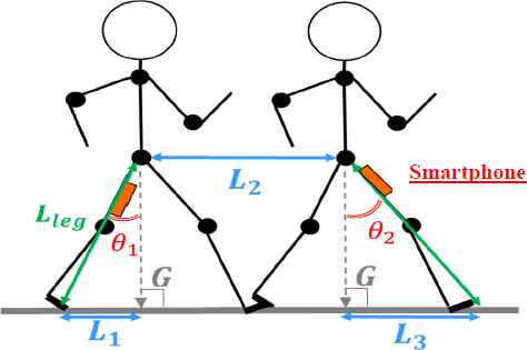
One stride image.
Then, L2 is obtained using Eq. (4). The r is representing the width of the waist.
In Fig. 2, “θ” is representing an angle due to the rotation in the transverse plane, and it can be calculated using Eq. (5). The rotation of the cross section is expressed by a value “gy” of Y-axis gyro sensor. The integration interval can be determined by the values that form the Y-axis and Z-axis of the acceleration sensor. It is from the moment t0 at which the foot is pulling the most backward until the moment t1 when the foot is stepped forward and landed, or from the moment of landing to the moment when the foot reaches the back. After calculating the rotation angle, the distance calculated from the rotation of the lumbar region can be calculated by using the expression for obtaining the string of the circle. Therefore, if the desired stride is L, the stride is estimated by Eq. (6). We call the proposed method 1 about the stride length of Eq. (6).
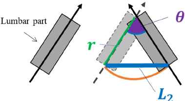
Correction amount by rotation of waist.
4. How to judge walking
To build a system that calculates the stride from walking motion, it is necessary to estimate the state that a person is walking. Therefore, in this section, we describe the walking judgment method of a person.
4.1. Method of attached the smartphone
In order to determine the walking state, the inclination of the smartphone is calculated from the value of the acceleration sensor. The inclination of the device can be used directly to track the movement of the thigh. From this reason, we can capture the periodic movement of the walking thigh. The smartphone is attached to the thigh using a supporter as shown in Fig. 3(a) and the axis information of the smartphone is shown in Fig. 3(b). At this time, the smartphone should not be turned upright and must be worn with the display facing in the direction of walking. Although the direction of the device is limited, calibration for determining the axis of the sensor used for calculating each parameter by this mounting method becomes unnecessary. Therefore, the subjects can start walking with free timing.
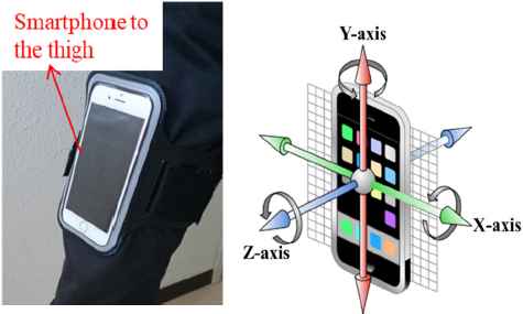
Position to install smartphone.
The smartphone iPhone 4S (iOS 7.0) used for this research has a function capable of detecting gravitational acceleration. The inclination angle (rad) of the device can be calculated from the detectable gravitational acceleration on the Y axis and the Z axis by Eq. (7).
4.2. Walking conditions
Experimental conditions are shown in Fig. 4. Before starting to walk, the subject stands upright with both feet aligned and starts walking from the right foot. Walk three steps with the subject’s right foot as the first step and calculate the walking distance at the third step. Next, walking is stopped by aligning the left foot of the fourth step with the right foot of the third step.
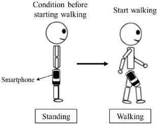
Walking conditions.
The example waveform when a person walking can be seen in Fig. 5.
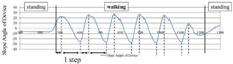
Device tilt during walking.
The periodic waveform indicates walking is occurring, but it may not be determined that the subject is walking. It is because there are individual differences such as forward inclination and backward inclination in the posture. When the inclination angle of the device is within ± 10 (degree), it is judged that the subject is standing. Fig. 5 “walking” showed that a positive value represents a state when the foot is stepping forward and a negative value represents a state when the foot is pulled backward. Therefore, in this paper, from the positive peak to the positive peak or from the negative peak to the negative peak is taken as the stride length (1 step).
5. Method of judging landing
The Y-axis value and the Z-axis acceleration sensor are used to determine the landing (hereinafter “acceleration YZ”). The YZ acceleration value is not the acceleration of gravity used in the determination of the subject acceleration produced by the subject. As shown in Fig. 3(a), when the smartphone is installed on the thighs, the magnitude of the acceleration YZ represents the acceleration in the sagittal plane. Fig. 6 shows that the slope of the smartphone and YZ acceleration during walking.
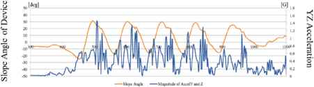
Changes in the magnitude of YZ acceleration
Fig. 6 shows that it is quite difficult to find features when landing. However, by disassembling into each quadrant as shown in Fig. 7, the feature amount at landing can be measured.
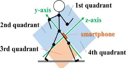
Device axis and quadrant as seen from sagittal plane
Fig. 8 shows that the waveform of YZ acceleration when Fig. 6 is divided into four quadrants.
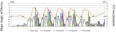
Quadrant decomposition of the magnitude of YZ acceleration
In order to see what type of YZ acceleration is occurring in what kind of motion, it can compare the tilt of the device tracking the movement of the foot with the YZ acceleration in Fig. 8. First, when the inclination of the device is near from the peak of the downward convex, it means YZ acceleration enters the third quadrant. When the tilt of the device is negative, the foot is in the state of being pulled to the back most, and that state can be said to capture the acceleration of the kicking leg. Next, the YZ acceleration takes the fourth quadrant. It means that the fourth quadrant is oriented mainly in the direction of walking, which shows that it captures the movement in the process of stepping forward. Next, take the first quadrant. It can be seen in Fig. 8 that the first quadrant means upward when steps are taken. It means that the force in the direction of walking weakened. Then, after the first quadrant, move the foot in the third quadrant direction representing the lower part of the thigh. This means the moment of landing. After the third quadrant, which means landing, the waveform is slightly disturbed, but the device vibrates after landing.
Therefore, the landing assessment is performed using the first peak of the third quadrant that occurs temporarily because the slope of the device is 10 (degree) or more (shown in Fig. 9). The value of 10 (degree) is to prevent peak misrecognition.
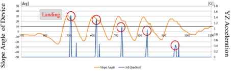
YZ acceleration in the third quadrant only
6. Experimental Results
In this section, we show the result of stride estimation. We experimented with simultaneous measurements between kinect and smartphone sensors. The number of subjects is 54 (Men: 12, Women: 42) at the age of 20 to 60. The proposed method 2 is a hybrid with the previous research 1 and proposed method 1. If the waist rotation exceeds 12cm, we used the proposed method 1, else used previous research 1. This is based on the results calculated from preliminary experiments, when the waist rotation amount exceeds 12 cm, the stride had a tendency to decrease error.
Fig. 10 can be seen that the proposed method 2 is better than in previous research 1 and proposed method 1. From this fact, it is assumed that the method of combining the sagittal and transverse fields more accurately captures motion rather than a method that only focuses on the sagittal plane.
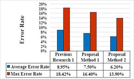
Estimation accuracy of each strides estimation method.
7. Experimental Results 2
In this section, by using the proposed method 2, we investigated the problem which occurs at the time of walking uphill and the sensor showing the characteristics of ascending slope walking.
For climbing experiments, we use the experimental hill climbing model as shown in Fig. 11. The hill-climbing model is designed to secure a walking distance of 2 m with 0 degree, 10 degrees, 20 degrees and 30 degrees. By using the model and determining the walking condition, it becomes possible for the subject to carry out the experiment smoothly.
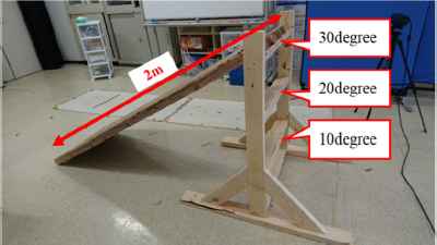
Experimental climbing model.
7.1. Changing method of landing determination
Fig. 12 shows the difference in landing timing. The vertical axis is the of the device, and the horizontal axis is the number of data. Also, peak 1 is the proposed method 1, and peak 2 is the determination by “the time when the device is the most inclined is the landing”. When peak 1 and peak 2 are value of 1, it means that it is judged as “landing”. The value of acceleration changes from the difference in walking motion due to the inclination. As a result of the experiment, we found that the landing determination by the YZ acceleration cannot judge that the first peak in the third quadrant is the landing timing. From this result, we considered that it is difficult to make landing determination by the same method. Therefore, using the method of the previous study, the landing determination was made to judge that “the time when the device is the most inclined is the landing”.
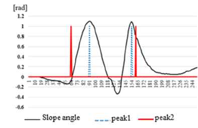
Landing determination timing method.
7.2. The correction formula using the value of gravity acceleration Y-axis
Next, we will describe the sensor value. Fig. 13 shows that the peak value in the positive direction of the gravitational acceleration Y axis increases as the inclination angle increases. This indicates that the swing-up motion of the thigh is getting bigger when walking uphill. From the experimental results, we confirmed that the error between the measured value and the true value also increased as the inclination angle became larger in the ascending slope walking. The verification results on this relationship will be described in detail in the experimental result of section 7.3.

The value of gravity acceleration Y axis.
7.3. The correction formula using the value of gravity acceleration Y-axis
In this section, the calculation result of the correction equation will be described. The results are shown in Fig. 14, and the horizontal axis represents the gravitational acceleration Y axis, and the vertical axis represents the error between the true value and the calculation result. In Fig. 14, × indicates 0 degrees, ▲ indicates 10 degrees, ■ indicates 20 degrees, and ♦ indicates 30 degrees. Experiment method and environment are the same as in section 4, and there are 3 subjects. Table 1 shows the average of the error rates according to each slope when this correction formula is not used and the average of the error rates when using the correction formula.
| No correction | With correction | |
|---|---|---|
| 30º | 97.0% | 10.3% |
| 20º | 65.3% | 10.7% |
| 10º | 32.8% | 18.3% |
| 0º | 24.9% | 11.0% |
Average error ratio before and after correction.
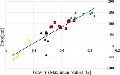
Calculation result of correction equation.
As a result, by using the correction formula calculated from all the subjects, 86.7% in the case of 30 degrees, 54.6% in the case of 20 degrees, 14.5% in the case of 10 degrees, and 13.9% in the case of 0 degrees were improved. In addition, the error rate as a whole was 12.6%. However, since the average error of 0 degree walking in the proposed method 2 was 7.5%, it was 3.5% worse in walking distance estimation at 0 degree. As a factor of worsening, it may be thought that the landing determination method was changed so as to be able to respond to the measurement of the ascent slope walking.
8. Conclusions
In this paper, the movement of the sagittal during walking motion that focuses on the movement of the cross-section, a method for estimating the step with high accuracy studied.
The results of proposed method 1 have the improvement rate of about 1.5% as an average error rate and the improvement rate of about 2.0% as a maximum error rate from previous research 1. The stride estimation method of proposed method 1 is more significant than the previous research 1.
Furthermore, the results of proposed method 2 have the improvement rate of about 2.8% as an average error rate and the improvement rate of about 4.5% as a maximum error rate from previous research 1.
By classifying walking based on the amount of rotation of the lumbar region, it was possible to estimate according to individual differences, and improvement of versatility was confirmed. From these results, the error rate of our proposed method 2 with the stride estimated by Kinect sensor (RGB-D sensor [2]) as the true value was about 6.2%, making it possible to estimate the stride with high accuracy.
In the case of ascending slope walking, we confirmed that the error between the measured value and the true value increases as the inclination angle increases. From the result, as a result of calculating the error by the correction formula using the value of the gravitational acceleration Y axis, 86.7% at 30 degrees, 54.6% at 20 degrees, 14.5% at 10 degrees, 13.9% at 0 degrees were improved.
References
Cite this article
TY  - JOUR
AU  - Hiroki Tamura
AU  - Keiko Sakurai
AU  - Koichi Tanno
PY  - 2018
DA  - 2018/09/30
TI  - A Study on High Accuracy Stride Estimation on Smartphone Combining Acceleration Sensor and Gyro Sensor
JO  - Journal of Robotics, Networking and Artificial Life
SP  - 83
EP  - 88
VL  - 5
IS  - 2
SN  - 2352-6386
UR  - https://doi.org/10.2991/jrnal.2018.5.2.2
DO  - 10.2991/jrnal.2018.5.2.2
ID  - Tamura2018
ER  -