
Attitude Control of Microsatellite Using PWM Method: Verification Using PIL
- DOI
- 10.2991/jrnal.k.201215.007How to use a DOI?
- Keywords
- Three axis magnetometer; earth magnetic field; Kalman filtering; processor-in-the-loop
- Abstract
The missions of micro-satellites range from early military usages to weather forecast, resources exploration, communication, and scientific experiment. The advantages of micro-satellites are simple mechanical structures, great reliability, low prices, and precise researchers and equipment. Therefore, due to the limits of weight and power, this kind of micro-satellite with low design cost and high precision requires reducing unnecessary attitude sensors and controllers to ensure the precision of attitude control. Besides, it adapts the least hardware constituting attitude system, which is the future trend in the satellite engineering. In this article, an estimating technology about measuring angle speed with a gyro less is mentioned. This technology is based on the period change which the earth magnetic field gets along the track. Only by using a three axis magnetometer, it can produce the data from the micro-satellite measuring the earth magnetic field. Besides, the measures of three axis angle speed and attitude angle can be gotten through Kalman filtering. The purpose of this article is mainly to explore the problem on attitude detumbling control of micro-satellites departing away a carrier to enter a track. It is realized by a thruster to proceed the confinement of the satellite moving, the attitude stable control and processor-in-the-loop.
- Copyright
- © 2020 The Authors. Published by Atlantis Press B.V.
- Open Access
- This is an open access article distributed under the CC BY-NC 4.0 license (http://creativecommons.org/licenses/by-nc/4.0/).
1. INTRODUCTION
Before the satellite departs away the carrier into the mission track, it will tumble with a high speed rotating attitude. Or before the initial rotating speed exceeds the designed tolerant value, the function of the attitude control system lies to confine tumble and lower the angle speed for the satellite to achieve the pointed location. If the attitude control system uses a thruster to correct the attitude, the advantage is that it is beyond the limits of outer circumstances and easy to operate. In addition, it is suitable for any controlling methods, fast to correct time, and precise to point. (1) The uncertainties in the interior satellite are there is an error in the setting distance of the spray head, the inclined side of the spray head is not accurate, and the usage of gas fuel makes the quality center deflect. (2) The exterior disturbances of the satellite are the height and position to the environmental factors: gravity gradient, air resistance and magnetic forces. (3) Using the spray head easily produces bang–bang control. It is impossible as a linear switch to have high fuel efficiency, which can use the pulse-width pulse-frequency modulation to solve the thruster problem at the same time [1,2].
As to a micro-satellite with lower precision to three axis point, lighter carrier, low power consumption and limited research charge, there is undoubtedly a good inducement to merely use the magnetometer to complete the three axis attitude and the speed of the attitude angle. Therefore, it is practically important to develop this engineering. In the past, the magnetometer is often used as an assistance to meet with other parts in the satellite attitude confirming system. It is less to use a single magnetometer to complete attitude confirmation. The main reason is that the attitude precision is limited by using this method. It cannot get rid of the error limitation from incorrect terrestrial magnetism. This common method is to use the star pattern to get the track parameter and then pass through International Geomagnetic Reference Field to find our local geomagnetic field [3], which compares with the magnetometer measuring value to get the attitude angle by the attitude algorithm. However, by doing so, it only can get two axis attitude angles, but it cannot provide the message of the angle efficiency. To get satellite upper angle efficiency, it is necessary to use a gyroscope. However, the function of the gyroscope will be worsened with time, and its price is high and the equipment is complicated. Therefore, it may be a good choice to adapt attitude angle sensor instead of a gyroscope. In the article, the formula of micro-satellite and exercise is calculated by quaternion and angle speed. In it, an unscented Kalman filtering is adopted. The purpose of the article focuses on (1) Designing the thruster position, (2) Taking the satellite attitude angle speed and four-element position as an order of thruster, (3) Considering when there is an error in the distance of the thruster position, the uncertainty in the interior satellite is the quality center change by using gas fuels, (4) Exterior disturbances are: satellite height and position to magnetic force, gravity gradient, and air resistance, (5) Using the thruster with the pulse-width pulse-frequency modulation to solve the thruster problem. (6) Describing the above questions by the leaning differential inequality [4,5], which means to reduce the exterior disturbances and limit the system parameter uncertainty of the satellite attitude controller.
The contents of the article are as follows: Section 2 problem description, the Thrust force derived of satellite in Section 3, Section 4 pulse-width pulse-frequency modulation rules, Section 5 Kalman filtering and different calculating methods, Section 6 fulfillment of Processor-in-the-Loop (PIL), and future prospects and conclusions in the last section.
2. PROBLEM DESCRIPTION
Considering satellite attitude exercise formula
Satellite non-linear dynamics formula
- (i)
The above is a quaternion, which is to rotate an Euler angle by order to a new attitude.
Suppose the specific condition is
- (ii)
- (iii)
- (iv)
J + ΔJ is inertial matrix,
In it, Iii is i axle rotates inertial, and εIij is i axle rotates inertial along j axle. When the fuels are used, they will the quality center in the satellite system, which are uncertain items in the satellite system parameter.
- (v)
τw represents that the satellite will be disturbed by the force, including gravity gradient force, air resistance force, and magnetic disturbed force.
- (vi)
τu represents satellite attitude controlled force. In the paper, the control theory is conducted to get the relationship τu thruster matrix and output u, and then is combined Pulse-Width Modulation (PWM) and the jet to produce thrust.
3. PRODUCTION OF SATELLITE THRUST
The satellite configure frame is as Figure 1. Four thrusters are put xy plane, including δ angle, the jet moves toward −z direction, and lines to be a square distance d1. Fuel is put the jet xy plane d2 distance, and +z direction is toward satellite center, in Figure 2. εδ, εd1 and εd2 respectively represent the jet including angle, jet relative distance, and the uncertainty of the fuel gravity position. The following is production τu from the thruster:
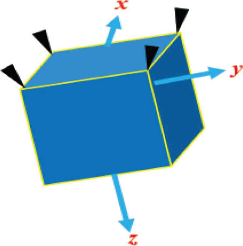
Satellite external configure frame.
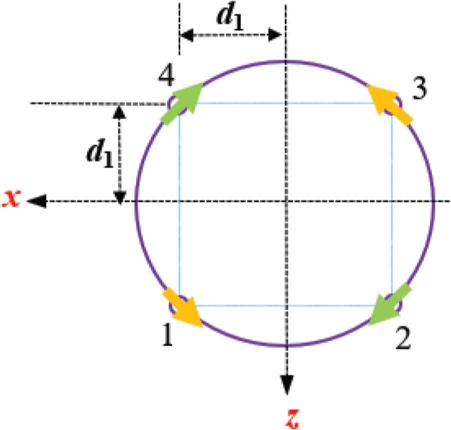
Satellite jet geometry frame.
When the thruster transfers matrix B, the features are as follows (Micro-satellite pulse-width modulation thruster attitude control shown in Figure 3) [6].
- 1)
- 2)
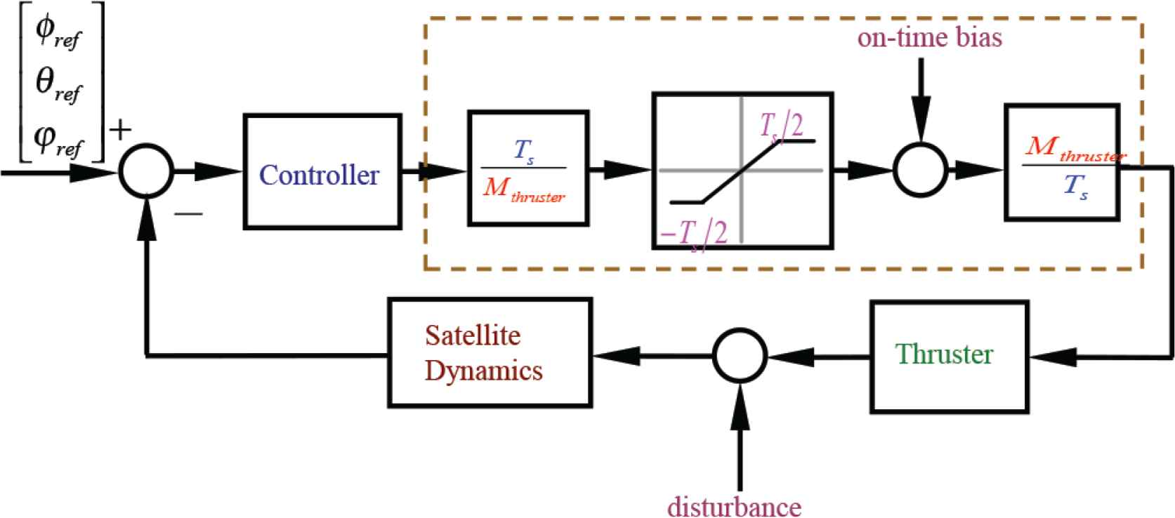
Micro-satellite pulse-width modulation thruster attitude control block diagram.
4. PULSE-WIDTH MODULATION RULES
According to the thruster and PWM, the period can be divided into two modulations: off-modulation and on-modulation, Figure 4 illustrates the PWM process. From it, there is at least one truster works in the off-modulation, while there is at least one truster does not work in the on-modulation. In this project, an on-modulation is adopted.
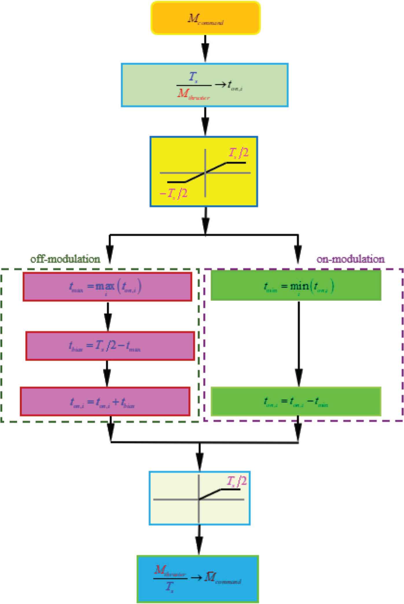
Pulse-width on/off modulation control process block diagram.
5. PROCESSOR-IN-THE-LOOP
Because the software loop cannot be completely tested in attitude measuring elements and the thruster, the PIL in the second stage is needed [6,7]. In Figures 5 and 6, the structure of the PIL.
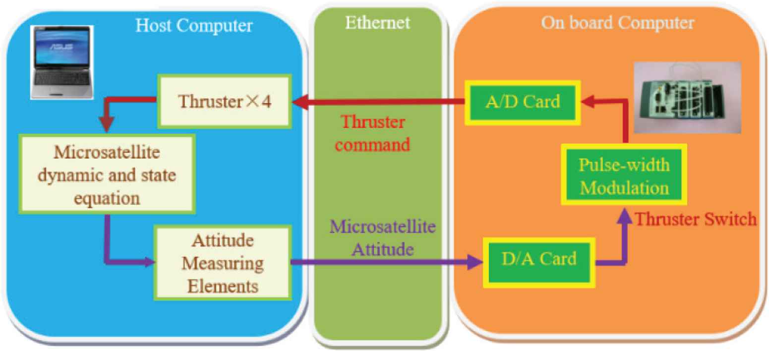
Processor-in-the-loop system block diagram.
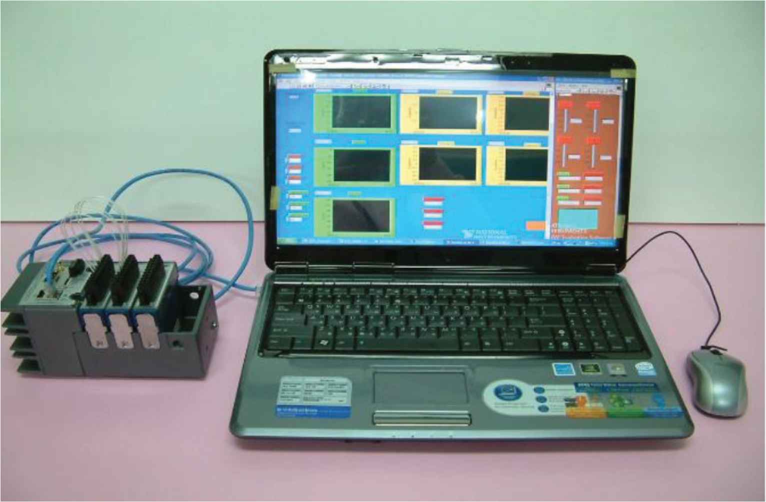
Photos of processor-in-the-loop system hardware devices.
The operation architecture of gyro less [8] combine with Unscented Kalman filter (UKF) algorithm is shown in the block diagram (Figure 7).
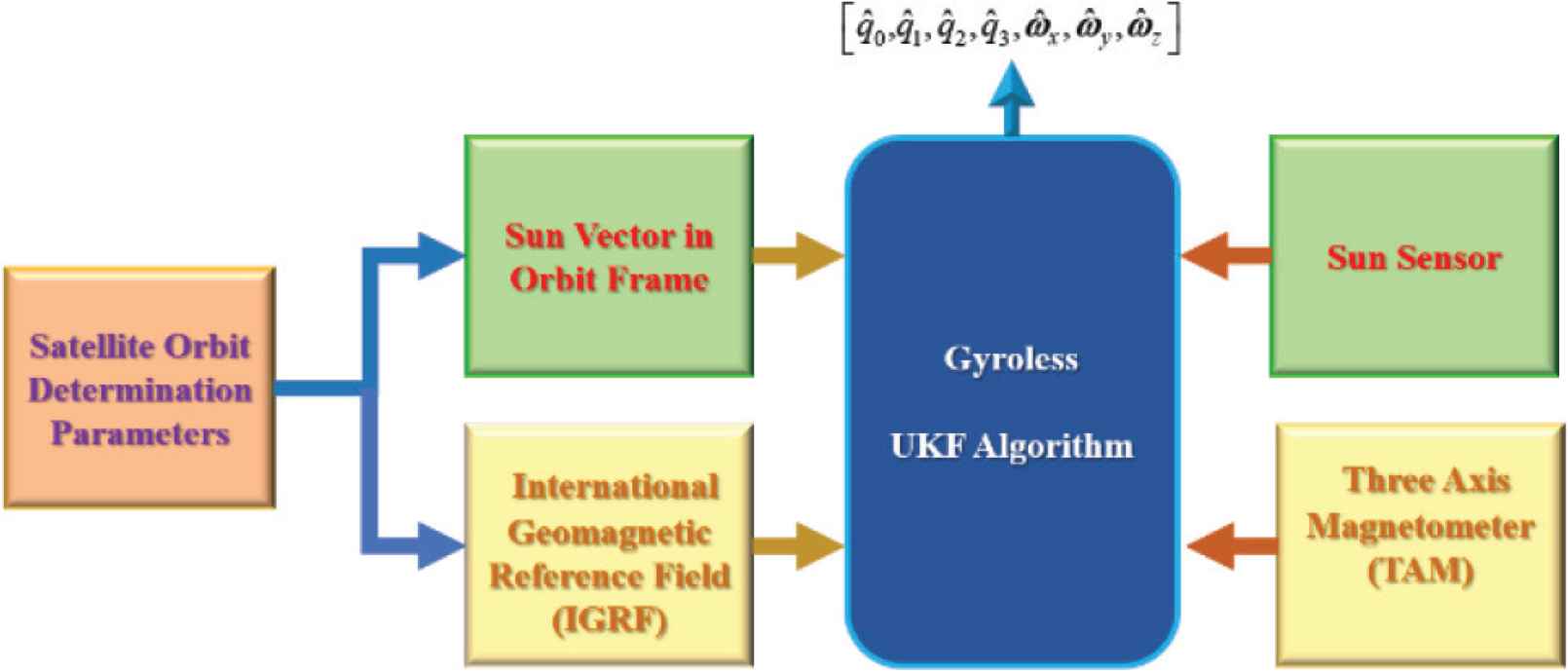
Block diagram of operation architecture of gyro less with UKF algorithm.
The content of the experiment will use the satellite parameters of Tables 1 and 2 the initial conditions to simulate the satellite attitude response.
| Item | Uncertainty bound | Value | Unit |
|---|---|---|---|
| δ | εδ/δ = ±0.1 | 5 | deg |
| d1 | εd1/d1 = ±0.1 | 0.25 | m |
| d2 | εd2/d2 = ±0.1 | 0.24 | m |
| Iii | εIxx/Ixx = ±0.1 | 5.5384 | kg/m2 |
| Iyy | εIyy/Iyy = ±0.1 | 5.6001 | kg/m2 |
| Izz | εIzz/Izz = ±0.1 | 4.2382 | kg/m2 |
Parameters of microsatellite
| Item | Description | Value | Unit |
|---|---|---|---|
| [φ, θ, ψ] | Initial Euler angle | [−120, 30, 60] | deg |
| [q1, q2, q3, q4] | Initial quaternion | [0.0474, 0.5303, −0.6597, 0.5303] | – |
| [ω0x, ω0y, ω0z] | Initial angular rate | [3.5, −3.5, 0.23] | rad/s |
| dt | Step time | 1.0 | s |
| Tsim | Simulation time | 1200 | s |
Initial conditions of microsatellite
CONFLICTS OF INTEREST
The author declares no conflicts of interest.
ACKNOWLEDGMENTS
This work was supported by the National Science Council of Republic of China under contract NSC 107-2221-E-344-002 and the construction technological advice, assistance, and financial support.
AUTHOR INTRODUCTION
Dr. Ho-Nien Shou
 He received the PhD degree in Electrical Engineering, both from National Cheng Kung University, 2002. From 1999 to 2001, he was with the National Space Organization (NSPO) as an assistant researcher, working with satellite attitude control system. Currently, he works as an Associate Professor at Department of Aviation & Communication Electronics Air Force Institute of Technology. His main research interests include Artificial Intelligence, nonlinear system control, satellite attitude control system.
REFERENCES
Cite this article
TY  - JOUR
AU  - Ho-Nien Shou
PY  - 2020
DA  - 2020/12/31
TI  - Attitude Control of Microsatellite Using PWM Method: Verification Using PIL
JO  - Journal of Robotics, Networking and Artificial Life
SP  - 245
EP  - 248
VL  - 7
IS  - 4
SN  - 2352-6386
UR  - https://doi.org/10.2991/jrnal.k.201215.007
DO  - 10.2991/jrnal.k.201215.007
ID  - Shou2020
ER  -