
Development of the Feed Part Control System for Rectification Process
- DOI
- 10.2991/jrnal.k.191202.005How to use a DOI?
- Keywords
- Rectifying column; feed; PLC; PID
- Abstract
This paper completes the structure design of the feed process for the small rectification experimental unit. According to the process requirements, the overall scheme of the detection and control system and the main parameters are designed, and the type of the instrument is selected. The system hardware design is based on the CPU222 of Siemens s7-200 PLC (Programmable Logic Controller) and the corresponding input/output module. The lower computer adopts STEP 7-Micro/WIN programming software, and it completes the program design of parameter acquisition, scale transformation and PID (Proportion Integration Differentiation) operation through ladder diagram. The monitoring interface of the upper computer adopts Kingview monitoring software.
- Copyright
- © 2019 The Authors. Published by Atlantis Press SARL.
- Open Access
- This is an open access article distributed under the CC BY-NC 4.0 license (http://creativecommons.org/licenses/by-nc/4.0/).
1. INTRODUCTION
The rectification operation needs the different volatility for different components of the mixed liquid under the same pressure, and it causes the partial vaporization and condensation of different components in the column, and finally the complete separation is obtained [1]. For a long time, the control of the rectifying column has been one of the research hot spots. Several control strategies are proposed, such as the fuzzy controller with self-learning capability for achieving the control of a binary methanol-propanol rectifying column [2].
The developed system is mainly aimed at the feed part of the rectifying column. There are three feed states of rectifying column: superheated steam, supercooled liquid mixed in vapor-liquid phase and saturated liquid. Feed quantity, temperature, pressure and material balance are the important factors that affect the rectifying column [3]. For the feed flow, the method to increase the liquid holdup in the feed plate through a middle vessel has been proposed [4]. The choice of the feed temperature should be considered from the perspectives of both the total annual cost and the dynamic control performance [5].
Considering the influence of the feed flow rate and feed temperature on the feed part, the design on the feed part control system of rectification process is based on the following:
First, the technological process of rectifying column and feed process is analyzed, and the process pipeline and control flow chart are drawn.
And then the detection and control points of the feed control system are determined to achieve the ideal rectification effect, and the instrument selection is completed.
Next comes to the design on the hardware. The selection of PLC modules and the hardware wiring of the system are mainly completed.
Finally, the software of the control system is developed. The STEP 7-Micro programming software manufactured by Siemens in Germany is used to write the control program to the lower computer through the ladder diagram programming language, so as to realize the collection and processing of field data, and control the communication between the field equipment and the upper computer. The upper computer adopts the monitoring software (such as Kingview manufactured by WellinTech in Beijing, China), which is compatible with the selected PLC to monitor the control process.
2. OVERALL SCHEME DESIGN
2.1. Analysis of Process Flow and Control
The process pipeline and control flow chart of feeding part is shown in Figure 1. The mixture is added into the feed tank V102, then the valve of VA107 is opened, and then the feed pump P102 feeds the raw material into the feed preheater E101 to heat the raw material. The feed flow meter FIC101 detects the feed flow in order to control its variation range. The valve VA112 is opened to allow the raw steam generated by the feed preheater to enter the rectifying column T101. TIC101 detects the feed temperature and controls the heating temperature of the feed preheater to obtain the target product. The raw materials and steam entering the rectifying column are subsequently reflux and reboiler treated to produce light component products and recombinant sub-products. After the rectification experiment, the residual liquid in the raw material tank was taken back to the tower kettle discharge tank V105 for recycling and utilization by vacuum pump P101 and vacuum buffer tank V101.
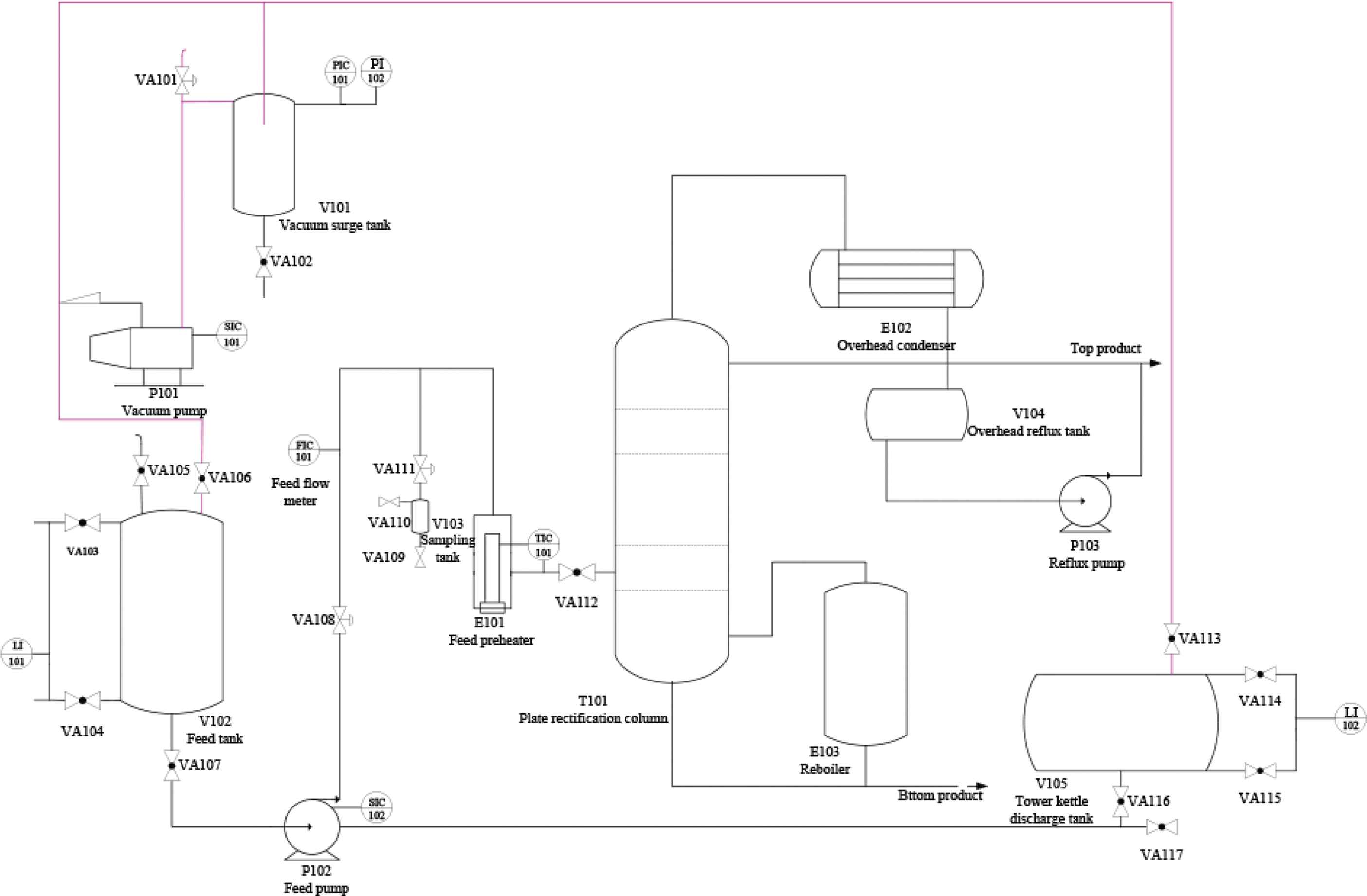
The process pipeline and control flow chart of feeding part.
2.2. Determination of Detection Scheme
First, the detection points are selected. There are many factors influencing the feed in the process of rectification, among which the temperature of feed and the flow rate of feed are the important factors influencing the whole process of rectification. The variation range of feed temperature will directly affect the vapor-liquid equilibrium of the whole rectifying column. The variation range of feed quantity should be controlled within a reasonable range to achieve the ideal rectification effect. In addition, the liquid level of the raw material tank should be tested in order to add the raw material in time. Therefore, the detection points are as follows:
- •
FIC101: feed flow.
- •
TIC101: feed temperature.
- •
LI101: feed tank level.
Next is the selection of the measuring instruments. The differential pressure flow transmitter, which is an intelligent differential pressure flow meter that is based on the monocrystalline silicon differential pressure sensor, is chosen for the flow detection point FIC101. It can display feed flow in real time and realize the remote transmission, which is convenient for remote real-time monitoring. The Pt100 temperature sensor, which not only has the analog signal output function of the transmitter, but also can increase the digital communication function, is chosen for the temperature detection point TIC101. The input level transmitter, which is a pressure sensor to measure the liquid level, is chosen for the liquid level detection point LI101. The essence of liquid level measurement is to change the pressure differential into 4–20 mA standard signal by sensor and amplifying circuit and then output it.
2.3. Determination of Control Scheme
According to the selected detection points, two control points are determined. First is the flow control point FIC101, which controls the feed flow by controlling the speed of the feed pump. The other is the temperature control point TIC101, which controls the temperature of the feed preheater by controlling the heating power of the heating rod. Therefore, the control points are as follows:
- •
FIC101: feed flow.
- •
TIC101: feed temperature.
Finally, the selection of actuators is completed according to the selected control points. For FIC101, the frequency converter is the one that controls the speed of raw material pump, so the Siemens MM440 frequency converter is chosen. For TIC101, the solid state voltage regulator is chosen to control the power of heating rod.
3. HARDWARE DESIGN
The input and output points of this control system include two digital input points (start and stop switches), two digital output point (two control relays), three analog input points (feed temperature, feed rate and feed tank level), two analog output points (voltage of the solid-state voltage regulator and frequency of the frequency converter). Therefore, the CPU222 module is selected, which has eight native digital inputs and six native digital outputs, allowing up to two I/O expansion modules. One EM231 analog expansion input modules and an EM232 analog expansion output modules are selected as required.
The hardware wiring diagram is shown in Figure 2.
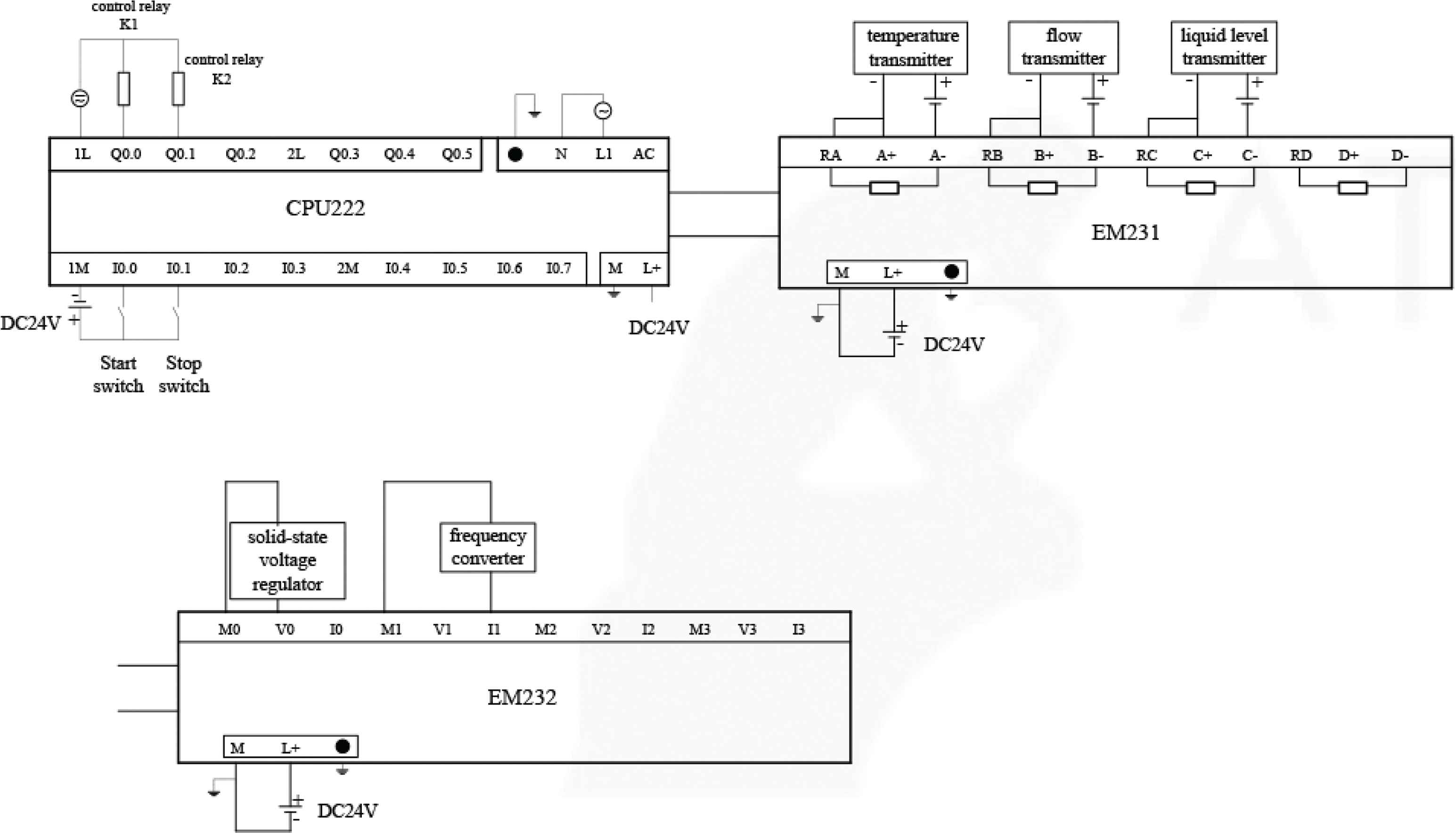
The hardware wiring diagram.
4. PROGRAMMING SOFTWARE DESIGN
The control layer of the feed part of rectification process is the PLC system. It is used to receive on-site data and control the site equipment according to the pre-designed control strategies, while sends the on-site data and equipment state to the PC machine. The S7-200 series PLC is selected as the controller, and the STEP 7-Micro/WIN software of the German SIEMENS company is used.
4.1. The Main Program Design
The PLC program is designed in a structured way. The main program completes all functions of the system, and calls each module in turn according to the system requirements and subroutine functions. The data conversion and scale conversion subroutine is used to process and store the collected data. Some of the data and the set value are compared to calculate the deviation, which is used for the PID operation. The control output conversion subroutine is used to transform the data after PID operation and output it to the executor. The flow chart of the main program is shown in Figure 3.
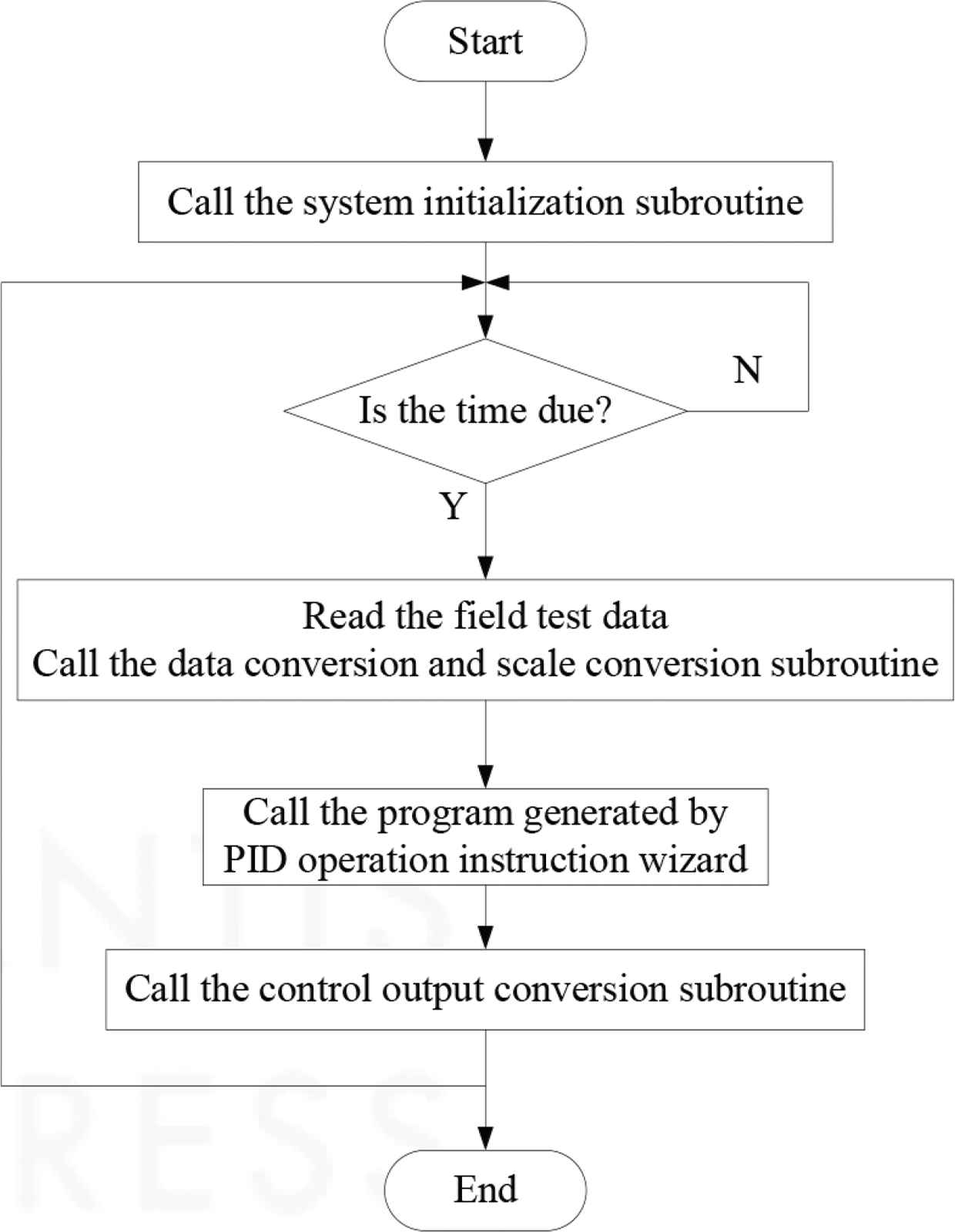
The flow chart of the main program.
4.2. PID Operation Subroutine Design
In practical engineering, the ratio, integral and differential control is the most widely used regulator control law, referred to as PID control, also known as PID regulation [6].
In STEP 7-Micro/WIN V4.0, the wizard can be used to generate a PID instruction or program, and then it is called by the main program [7]. After completing the configuration of the PID loop through the wizard, the specified PID regulation subroutine PIDx_INIT and interrupt program PID_EXE will be automatically generated. The PIDx_INIT instruction performs the PID function based on the inputs and outputs that have been previously set in the PID wizard, and it can be invoked every time the scan is performed. In this design, the feed temperature control system and feed flow control system adopt PID wizard to generate the instructions [8].
5. MONITORING SOFTWARE DESIGN
The Kingview6.55 is used as the monitoring software. Generally, such a system can be divided into three layers: the control layer, monitoring layer and management layer. PLC and PC are connected by the PC-PPI cable hardwire, and the monitoring software of PC is communicated with PLC through PPI, which is a communication protocol developed by Siemens for the s7-200 series PLC [9].
First of all, the external equipment is defined, and the communication between the Kingview6.55 and the external equipment is completed. Second, the variables in the control system is defined. Finally, the configuration screen, which includes the drawing of the screen and the connection of the animation, is designed. The configuration screen is divided into three pages, namely, the main interface for feed monitoring, the production report and the data curve. It is equipped with the start and stop button, the screen switch button, the user login and exit button, etc. The main monitoring interface after login is shown in Figure 4.
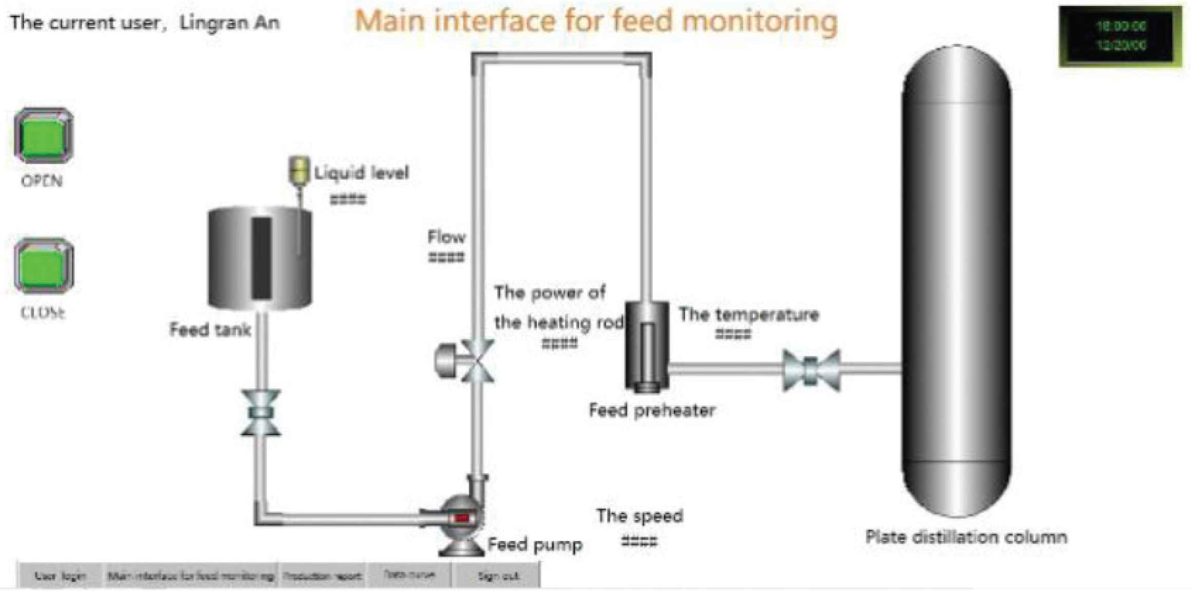
The main monitoring interface after login.
In the feed part monitoring software of the rectification process, the production report is used to record the data and status generated in the production process. The production report mainly includes the real-time production report and the historical production report. In real-time production reports, data is recorded every hour. Part of the data recorded in the real-time production report during the monitoring process is shown in Table 1. It shows that the values of the three detection points do not fluctuate greatly in a certain period of time, and the system has good stability.
| Real-time production report | |||
|---|---|---|---|
| Date | 2018/11/18 | ||
| Time | Feed temperature | Feed flow | Feed tank level |
| 14:00:00 | 83.50 | 107.90 | 4.70 |
| 15:00:00 | 84.20 | 108.50 | 5.40 |
| 16:00:00 | 83.90 | 108.20 | 5.00 |
The real-time production report
6. SUMMARY AND PROSPECT
The design adopts the DCS (Distributed Control System) control system based on programmable controller Siemens S7-200. Its contents mainly include the design on the feed part of the rectification process control system and the development of the hardware and software.
The detection and control points selected in this design are for the feed part of the rectification process, and the complete rectification process should also include the reflux and the reboiler part.
CONFLICTS OF INTEREST
The authors declare they have no conflicts of interest.
ACKNOWLEDGMENTS
The research is partly supported by
Authors Introduction
Dr. Fengzhi Dai
 He received an M.E. and Doctor of Engineering (PhD) from the Beijing Institute of Technology, China in 1998 and Oita University, Japan in 2004 respectively. His main research interests are artificial intelligence, pattern recognition and robotics.
He worked in National Institute of Technology, Matsue College, Japan from 2003 to 2009. Since October 2009, he has been the staff in Tianjin University of Science and Technology, China, where he is currently an Associate Professor of the College of Electronic Information and Automation.
Ms. Lingran An
 She is a third-year master candidate in Tianjin University of Science and Technology, majoring in numerical analysis, matrix theory, modern detection technology and other important control disciplines. Her research area is about deep learning and image processing. During her study, she has published several research papers.
REFERENCES
Cite this article
TY  - JOUR
AU  - Fengzhi Dai
AU  - Lingran An
PY  - 2019
DA  - 2019/12/12
TI  - Development of the Feed Part Control System for Rectification Process
JO  - Journal of Robotics, Networking and Artificial Life
SP  - 152
EP  - 156
VL  - 6
IS  - 3
SN  - 2352-6386
UR  - https://doi.org/10.2991/jrnal.k.191202.005
DO  - 10.2991/jrnal.k.191202.005
ID  - Dai2019
ER  -