
Tracking/Robust Trade-off Design of a Sampled-data PID Controller for Second-order Plus Dead-time Systems
- DOI
- 10.2991/jrnal.2018.5.2.10How to use a DOI?
- Keywords
- PID control; Sampled-data system; SOPDT system; Sensitivity function; Robust
- Abstract
In this paper, we propose a new design method of a second-order plus dead-time (SOPDT) sampled-data Proportional-Integral-Derivative (PID) control system, where the continuous-time plant is controlled using the discrete-time controller. The proposed control system is designed so that the tracking performance is optimized subject to the stability margin constraint. In the present study, the servo and regulation optimal controllers are designed. Finally, the effectiveness of the proposed method is demonstrated through numerical examples.
- Copyright
- Copyright © 2018, the Authors. Published by Atlantis Press.
- Open Access
- This is an open access article under the CC BY-NC license (http://creativecommons.org/licences/by-nc/4.0/).
1. Introduction
Proportional-Integral-Derivative (PID)1,2 control has been widely used in industry. Since the performance of PID control depends on the tuning parameters, additional tuning methods have been studied recently. Although the stability of a control system is critical, its tracking performance is also important. However, because of the trade-off relationship between stability and tracking performance, they cannot be optimized simultaneously. Arrieta and Vilanova3,4 proposed a simple PID tuning method that optimizes the tracking performance subject to a prescribed robust stability. In this method, the optimal PID parameters are decided based on a first-order plus dead-time (FOPDT) continuous-time system. In order to design a discrete-time control system, Tajika et al.5 proposed a design method for controlling a discrete-time FOPDT system. The present study discusses a design method of the PID controller for controlling a second-order plus dead-time (SOPDT) system, in which the continuous-time plant is controlled using the discrete-time controller. In the proposed method, both servo and regulation optimized control methods are designed. Finally, the effectiveness of the proposed method is demonstrated through numerical examples.
2. Description of the Control System
Consider the continuous-time controlled plant given as follows:
3. Definition of the Optimization Problem
As the constraint condition, the stability margin is defined using the sensitivity function, and the evaluation function for the tracking performance is also defined.
3.1. Constraint condition
The sensitivity function Sf(z−1) is defined as follows:
3.2. Evaluation function
In the present study, the evaluation function J is defined as the integral absolute error:
4. Controller Design
The PID parameters are optimized for a normalized system, and hence, dimensionless parameters are defined as τ = Lωn, h = Tsωn, κp = KpK, τi = Tiωn, and τd = Tdωn. The range of these parameters are set as 0.1 ≤ τ ≤ 1.0, 0.01 ≤ h ≤ 0.10, and 0.3 ≤ ζ ≤ 1.2. In the proposed method, the constrained optimal problem is preliminarily solved for a designated finite plant, which is defined by discrete τ, h, and ζ, and the data set in which the optimal normalized PID parameters for discrete τ, h, and ζ, is obtained. In Fig. 1, the obtained normalized PID parameters are plotted by ∘, where
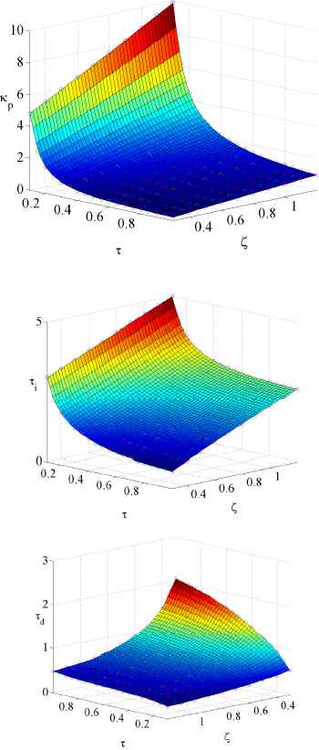
Relationships among τ, ζ and κp, τi and τd (servo design,
The desired normalized PID parameters for an arbitrary plant are decided by the linear interpolation from the data set. Practically speaking, the interpolated parameters are calculated using the nearest four points, as shown in Fig. 2. From this figure, the vector equation is obtained as follows:
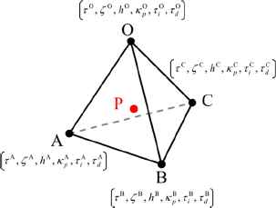
Image of the linear interpolation
| Servo design | Regulation design | |||||
|---|---|---|---|---|---|---|
| Min | Mean | Max | Min | Mean | Max | |
| 1.4 | 1.398 | 1.403 | 1.440 | 1.399 | 1.403 | 1.453 |
| 1.6 | 1.599 | 1.605 | 1.668 | 1.597 | 1.605 | 1.663 |
| 1.8 | 1.790 | 1.807 | 1.909 | 1.798 | 1.807 | 1.897 |
| 2.0 | 1.996 | 2.010 | 2.156 | 1.997 | 2.009 | 2.137 |
Obtained Ms
5. Numerical Simulation
In this section, the effectiveness of the proposed method is confirmed.
5.1. Control performance for various values of ζ
First, the control performance is confirmed for ζ. The controlled plant is defined as K = 4.2, ωn = 1.13, and L = 0.44 in Eq. (1), and Ts = 0.018. Here, we consider four pattern damping coefficients: ζ1 = 0.451, ζ2 = 0.69, ζ3 = 1.0, and ζ4 = 1.199. The control results are shown in Fig. 3. The reference value is set to 1.0, and the unit step disturbance signal is added after 20 s. Figure 3 shows that the proposed method is effective for under-and over-damping systems.
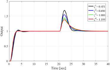
Output responses for each damping coefficient ζi (servo design and
5.2. Verification of stability margin
Next, the stability margin is confirmed. Here, the controlled plant is defined as K = 2.02, ωn = 0.91, ζ = 0.33, and L = 0.98 in Eq. (1), and Ts = 0.05. After 40 s, the dynamics is changed to K = 2.6, ωn = 1.3, ζ = 0.43 and L = 0.43 as the model variation. Furthermore,
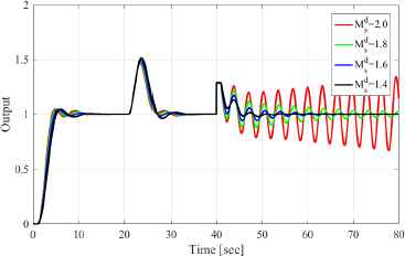
Output responses for each
Conclusion
In the present study, we have proposed a new design method for controlling an SOPDT sampled-data system, where the continuous-time plant is controlled by the discrete-time PID control law. In the proposed method, the PID parameters are designed for the normalized system, and the tracking performance is optimized subject to the assigned
Acknowledgements
The present study was supported by JSPS KAKENHI Grant Number JP16K06425. The authors would like to express their sincere thanks for the support from the Japan Society for the Promotion of Science.
References
Cite this article
TY  - JOUR
AU  - Ryo Kurokawa
AU  - Takao Sato
AU  - Ramon Vilanova
AU  - Yasuo Konishi
PY  - 2018
DA  - 2018/09/30
TI  - Tracking/Robust Trade-off Design of a Sampled-data PID Controller for Second-order Plus Dead-time Systems
JO  - Journal of Robotics, Networking and Artificial Life
SP  - 118
EP  - 121
VL  - 5
IS  - 2
SN  - 2352-6386
UR  - https://doi.org/10.2991/jrnal.2018.5.2.10
DO  - 10.2991/jrnal.2018.5.2.10
ID  - Kurokawa2018
ER  -