
Adaptive Sliding Mode Control of Inclination Angle and Tension for a Suspended Anti-Gravity Device
- DOI
- 10.2991/jrnal.k.210713.005How to use a DOI?
- Keywords
- Suspended anti-gravity device; microgravity; adaptive sliding mode control; ground verification
- Abstract
In this paper, the Suspended Anti-Gravity Device (SAGD) is studied to construct sustainable microgravity environment on the ground. To overcome the difficulty of accurate gravity compensation when SAGD is disturbed, a new adaptive sliding mode controller is proposed based on the dynamic model, which effectively ensures the stability of inclination angle and tension. The simulation and experiment results show that the transient time and steady-state error are small, which satisfies the requirements of spacecraft ground verification.
- Copyright
- © 2021 The Authors. Published by Atlantis Press International B.V.
- Open Access
- This is an open access article distributed under the CC BY-NC 4.0 license (http://creativecommons.org/licenses/by-nc/4.0/).
1. INTRODUCTION
In 2020, space probes such as “Perseverance”, “Chang’e-5” and “Tianwen-1” have been launched to explore Mars and the moon. It shows that human beings are marching toward deep space, ushering in a new era of rapid development of space technology. As we all know, it is difficult for human beings to reach space, which determines that the development of space technology is particularly dependent on ground experiments [1–3]. Since microgravity is the most important feature of space environment, many important devices have been developed to construct microgravity environment on the ground, including drop tower, air-floating platform, Suspended Anti-Gravity Device (SAGD), etc. However, the operation time and internal movable space of the drop tower and air-floating platform are limited. The SAGD offset the gravity of test object through the tension of hanging wire, breaking through the above limitations [4,5]. In the 1990s, Carnegie Mellon University developed an experimental device to verify various algorithms of space manipulator. The device uses counter-weight, pulleys and other mechanical structures to generate constant tension on the steel wire to offset the gravity of space manipulator. Subsequently, SAGD is concerned by many scientific research institutions [6]. Harbin Institute of Technology used single sling to offset five-sixths of the gravity of “YuTu” lunar rover, and measured its wheel pressure in a simulated lunar gravity environment. In 2019, Beijing Institute of Space Electromechanical Research developed a landing test device to verify the performance of probe during the landing phase in extraterrestrial body. It has been successfully applied to the landing test of Mars probe. The height of the device is 140 m, and the diameter of the experimental area is 120 m. By adjusting the tension of 36 steel wires, it can simulate the gravity environment of extraterrestrial body.
The SAGD has been widely applied. Therefore, it is significant to study how to keep the inclination angle and output force constant in the presence of disturbance. An Adaptive Sliding Mode Controller (ASMC) is proposed in this paper. Compared with the traditional method, the anti-interference ability of SAGD is improved.
2. SYSTEM MODELING
The SAGD consists of a horizontal servo system, a low stiffness structure, an unconstrained structure, a universal joint, a suspension system, and a test satellite, as shown in Figure 1 [5].
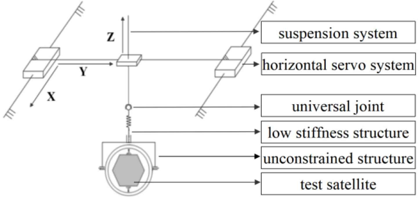
Schematic diagram of SAGD.
When the test satellite is disturbed, the horizontal servo system can quickly track its horizontal movement, and ensure that the low stiffness structure remains vertical. The universal joint and unconstrained structure can ensure that the freedom of test satellite is not restricted, so that the test satellite can perform approximate unconstrained pitching, yawing and rolling motion under a small frictional torque disturbance. The suspension system can control the output tension of SAGD by adjusting the moving distance of rack. A tilt sensor is installed under the universal joint to measure the inclination of low stiffness structure. Only when the inclination angle is 0 and the output force is equal to the gravity of test satellite, can accurate gravity compensation be realized and a long-term microgravity environment can be constructed. How to establish the coordinate system, please refer to Figure 2. O1 is the center of the gear in suspension system, O2 is the meshing point with rack. O3 and O4 are the center of universal joint and test satellite respectively. The physical meanings of the main symbols are as follows:
- •
g, Gravitational acceleration.
- •
R, Radius of the gear in suspension system.
- •
k, Elastic coefficient of low stiffness structure.
- •
ω, Inclination angle of low stiffness structure.
- •
L0, Initial length of low stiffness structure.
- •
L, Variation length of low stiffness structure.
- •
M, The sum of the masses of unconstrained structure and test satellite.
- •
Tα, Driving torque of the motor in suspension system.
- •
M1, M2, The loads on X- and Y-direction motor of horizontal servo system.
- •
Ma, Mb, The masses of the gear and rack in suspension system.
- •
Fx, Fy, Driving forces of X- and Y-direction motor of horizontal servo system.
- •
δx, δy, δz, Disturbing forces.
- •
ωx, ωy, Orthogonal decomposition values of ω.
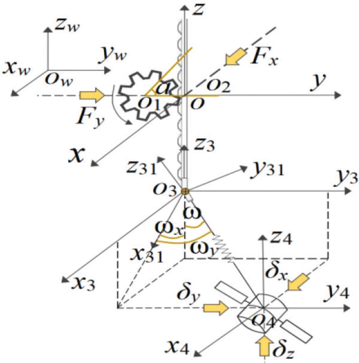
The coordinate system of SAGD.
According to the operation principle of SAGD, the model can be obtained by Lagrange equation.
The matrices defined in the model are as follows:
3. ASMC DESIGN
In this section, a new ASMC is designed, which can reduce the influence of uncertain disturbing forces on the accuracy of gravity compensation. Define variables:
The dynamic model (1) is transformed into
To offset the gravity of test satellite, and verify its attitude control performance in floating state, this paper defines the expected value of state vector q as qd = [0,0,0]T. The system error is e = q – qd, and the upper bound of
The switching function is defined as:
The adaptive parameter φ = [φ1, φ2, φ3]T is used in controller design to improve the anti-interference ability of SAGD. The adaptive law is defined as Equation (5), and φ is dynamically adjusted according to the value of switching function Equation (4).
Assumption 1.
The stable value
Theorem 1.
Under Assumption 1, the system error e will converge to 0, if the ASMC F is designed as:
When ėp = 0, define
Proof. The error of adaptive parameter φ is
Furthermore, the derivatives of Equations (4) and (7) can be obtained
Substitute the ASMC Equation (6) into Equation (8)
According to the analysis of Equation (9), the ASMC can stabilize the system. Substituting the controller Equation (6) into the system error model Equation (3), it can be found that the solution (e, ė) of the system error model will not make
4. SIMULATION ANALYSIS
In this section, to verify the ability of ASMC, the simulation experiment is carried out. Equation (10) is used instead of the sign function Sign(s) to reduce the oscillation of state response.
The parameters of the SAGD are R = 0.02 m, M = 15.5 kg, Ma = 0.52 kg, Mb = 4 kg, M1 = 16 kg, M2 = 41.5 kg, L0 = 0.45 m, k = 690 N/m. The pulse disturbance shown in Figure 3 is applied to the system.
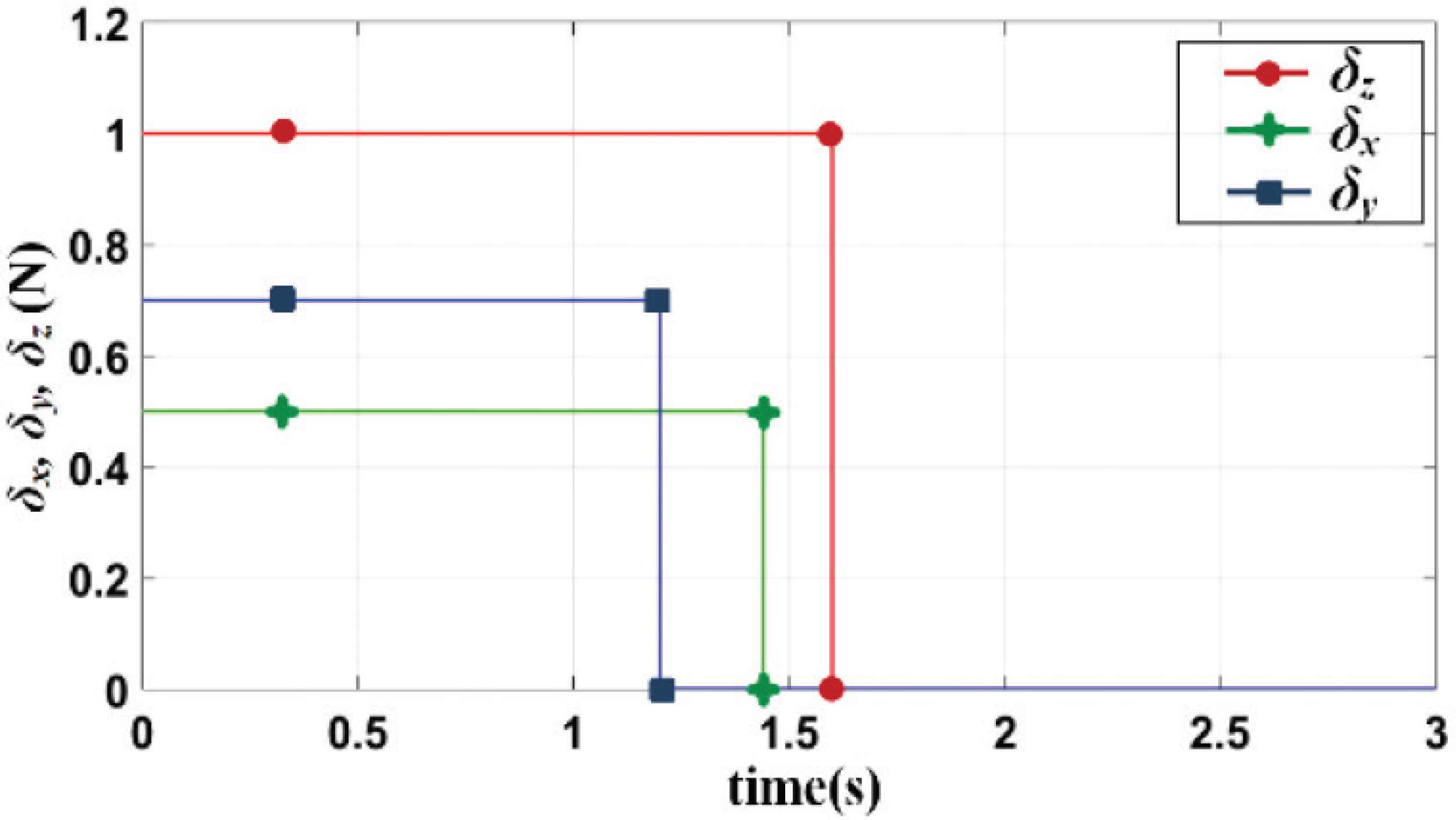
Disturbing forces.
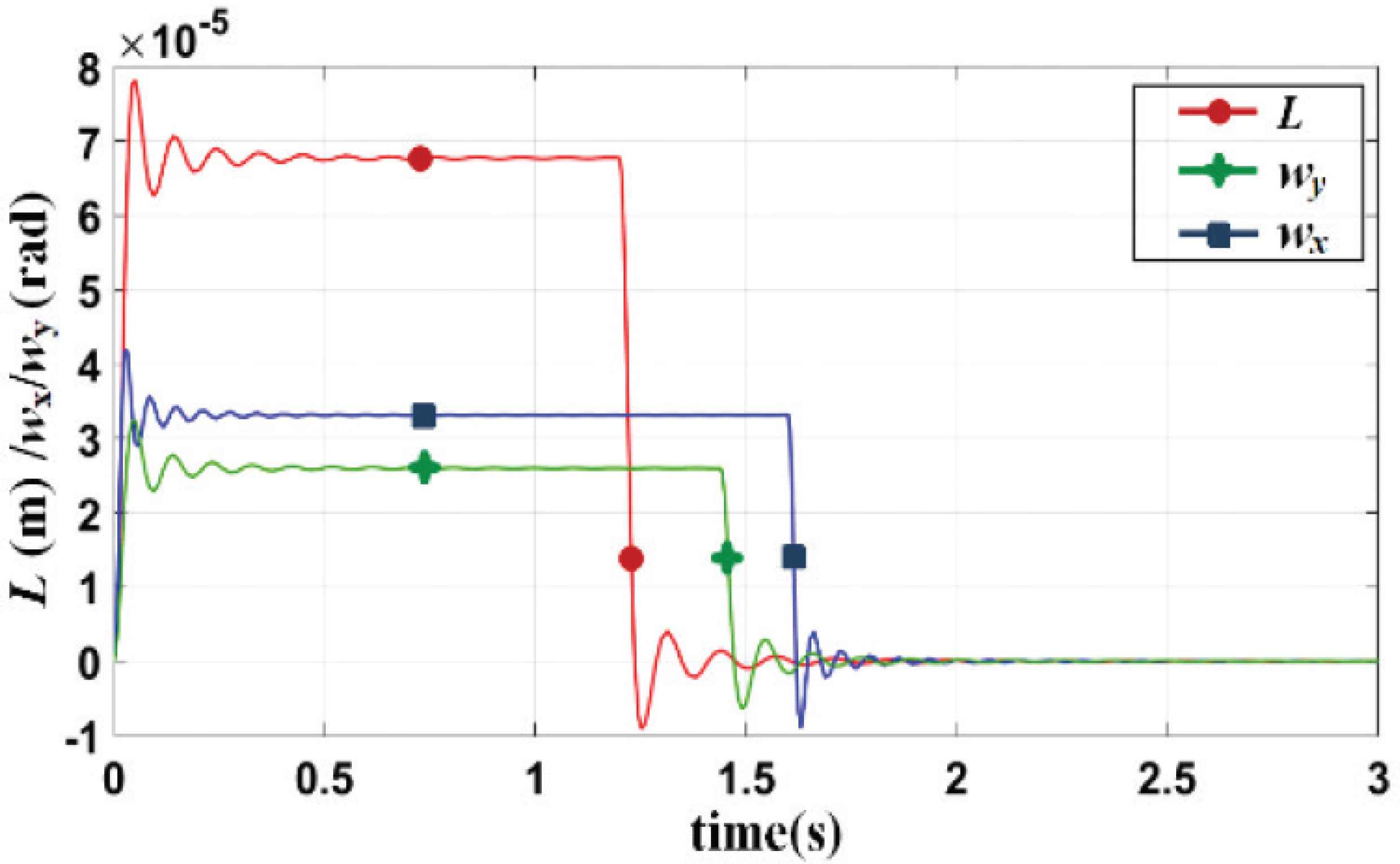
The simulation results are shown in Figures 4 and 5. It can be found that the maximum errors of L, ωx and ωy are 5.151 × 10⁻⁵ m, 3.779 × 10⁻⁵ rad, 1.254 × 10⁻⁵ rad, respectively. Therefore, the output tension error is 0.036 N, and the gravity compensation accuracy is about 99%. In the following, the ASMC is used to compare with the controller in Jia et al. [5]. By analyzing the results in Figures 4 and 6, it can be concluded that the transient time of the ASMC system is shorter and the steady-state error is smaller. When the simulation time t >1.6 s, the state error of ASMC system satisfies ||e|| < 4 × 10⁻⁶, while the control system in Jia et al. [5] needs 1.7 s. Furthermore, on the basis of disturbance, Gaussian noise obeying N(0,1) is added. The simulation results are shown in Figure 7, the state error satisfies ||e|| < 6.5 × 10⁻⁴, which still satisfies the requirements of ground verification.
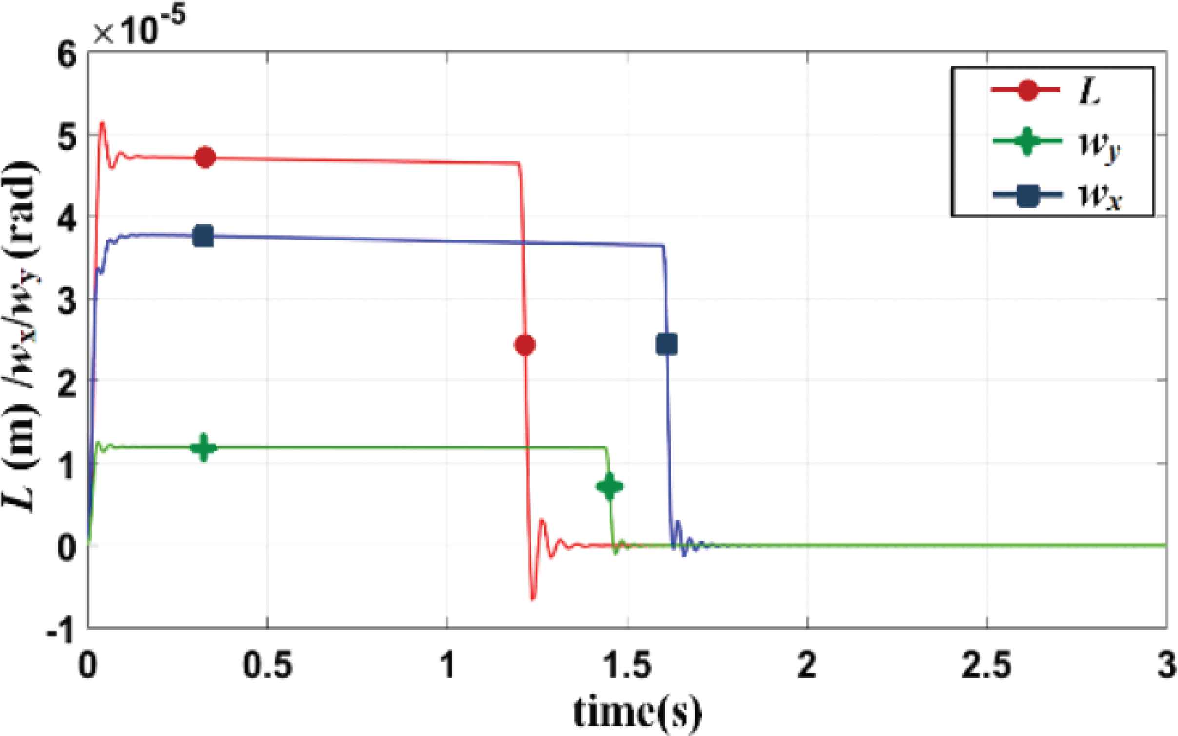
State response of the ASMC system.
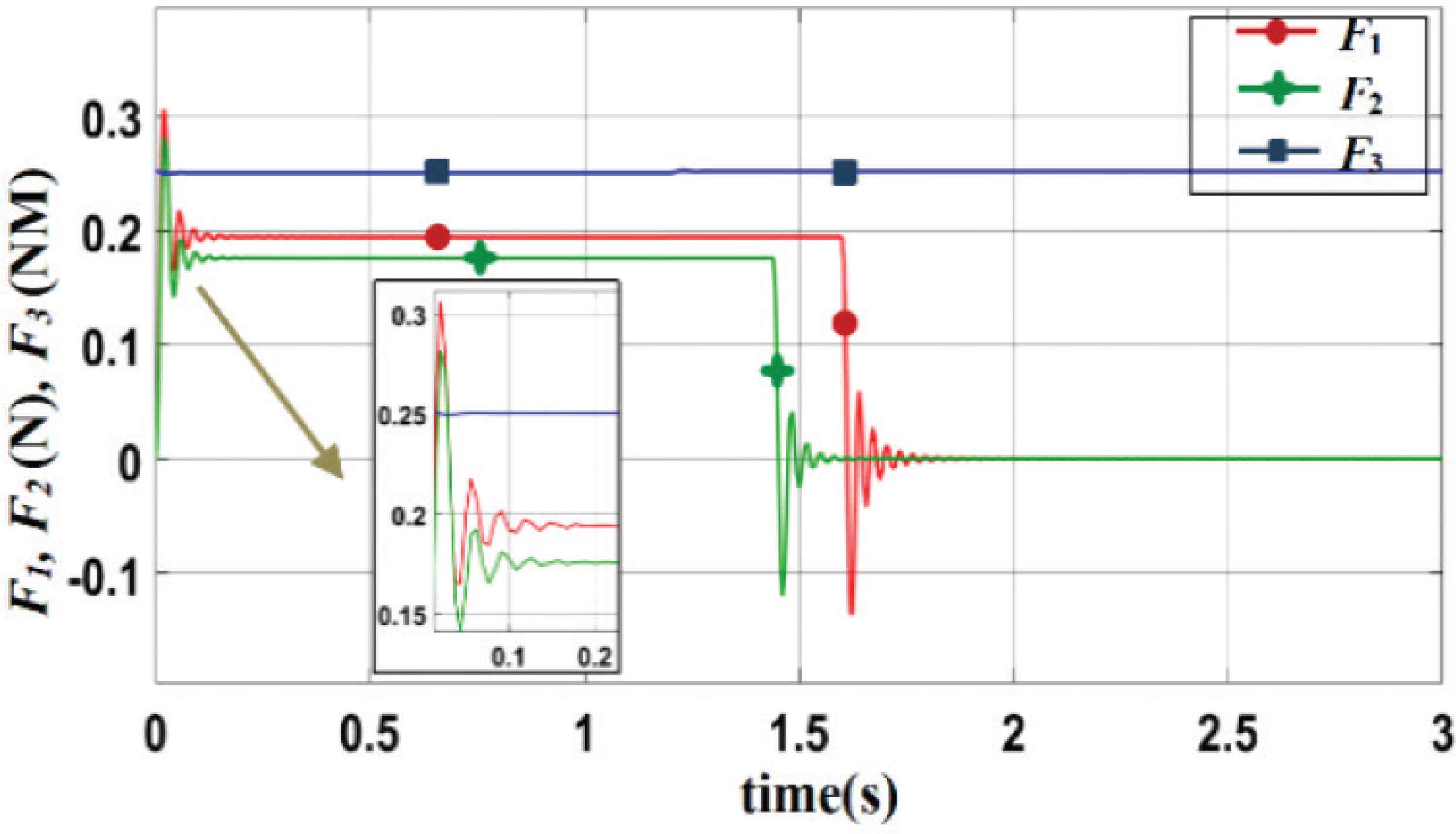
The output of ASMC.
State response of the control system in Jia et al. [5].
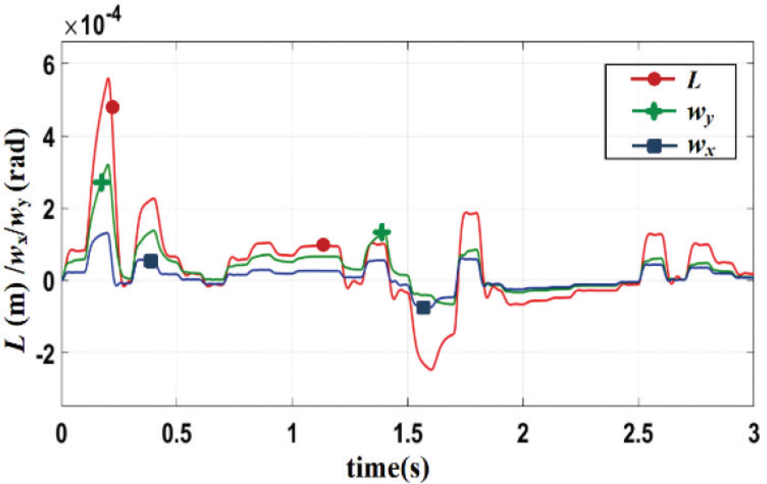
State response of the ASMC system with noise.
5. EXPERIMENT RESULTS
To further verify the superiority of ASMC proposed in this paper, experiments were carried out in the actual device shown in Figure 8. The experiment results are shown in Figures 9 and 10. The maximum errors of ωx and ωy are 0.55° and 0.18°, which means that the low stiffness structure remains approximately vertical. The expected value of force sensor output is Mg = 151.9N, and the maximum error is 9.1N. Therefore, SAGD can compensate the gravity with an accuracy of about 94%.
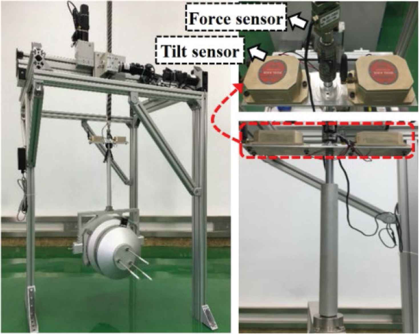
Suspended anti-gravity device.
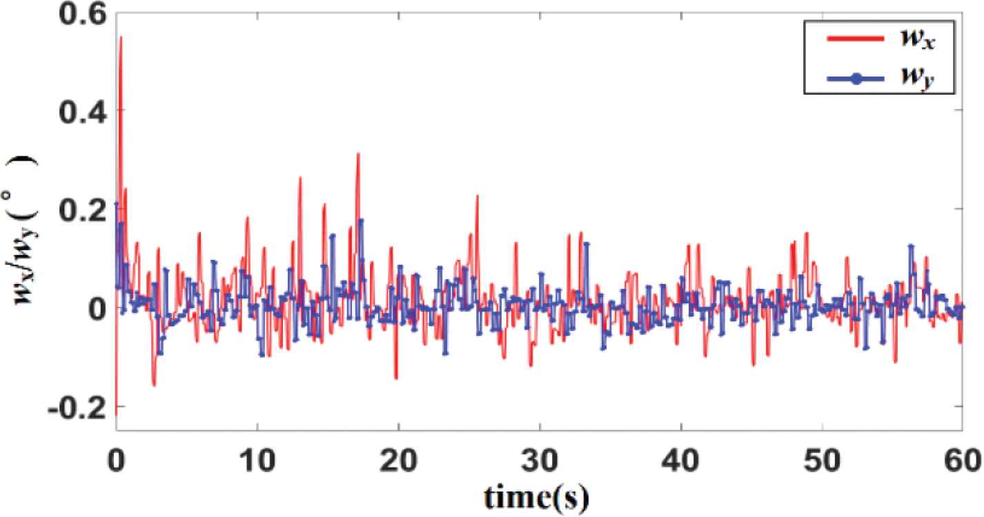
The output of tilt sensor.
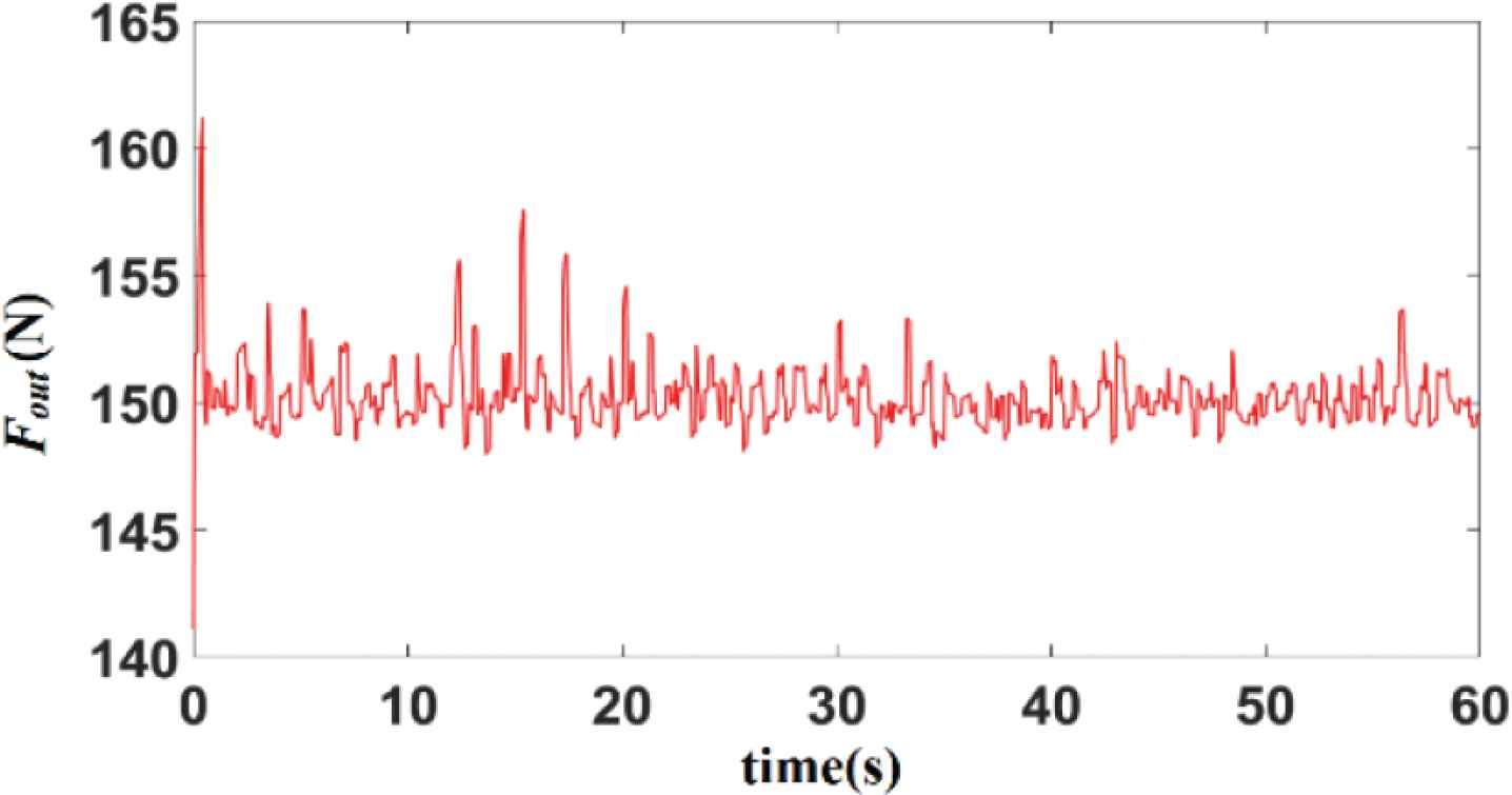
The output of force sensor.
6. CONCLUSION
In this paper, the dynamic model of SAGD is established by Lagrange equation, and then a new ASMC is proposed. The controller can make the system asymptotically stable, and overcome the difficulty of accurate gravity compensation in the presence of disturbance. The simulation results show that, compared with the existing methods, the ASMC has the advantages of small steady-state error and fast convergence speed. In addition, the performance of ASMC has been tested through the actual device, which can satisfy the requirements of ground verification.
CONFLICTS OF INTEREST
The authors declare they have no conflicts of interest.
ACKNOWLEDGMENT
This work was supported by the NSFC (61327807, 61520106010).
AUTHORS INTRODUCTION
Mr. Yuxin Jia
 He received the B.S. degree in automation from Chongqing University, China, in 2017. He is currently pursuing the PhD degree with the Seventh Research Division and the Center for Information and Control, School of Automation Science and Electrical Engineering, Beihang University. His current research interests include gravity compensation and intelligent control of robots.
Prof. Yingmin Jia
 He received the B.S. degree in control theory from Shandong University, China, in 1982, and the M.S. and PhD degrees both in control theory and applications from Beihang University, China, in 1990 and 1993, respectively. Then, he joined the Seventh Research Division at Beihang University where he is currently Professor of automatic control. He was the recipient of the National Science Fund for Distinguished Young Scholars in 1996, and was appointed as Chang Jiang Scholar of the Ministry of Education of China in 2004. His current research interests include robust control, adaptive control and intelligent control, and their applications in robots systems.
Mr. Kai Gong
 He received the B.S. degree in measurement & control technology and instrument from Harbin Engineering University, China, in 2016. He is currently pursuing the PhD degree with the Seventh Research Division and the Center for Information and Control, School of Automation Science and Electrical Engineering, Beihang University. His current research interests include motion and path planning for robotics and automation.
REFERENCES
Cite this article
TY  - JOUR
AU  - Yuxin Jia
AU  - Yingmin Jia
AU  - Kai Gong
PY  - 2021
DA  - 2021/07/22
TI  - Adaptive Sliding Mode Control of Inclination Angle and Tension for a Suspended Anti-Gravity Device
JO  - Journal of Robotics, Networking and Artificial Life
SP  - 94
EP  - 98
VL  - 8
IS  - 2
SN  - 2352-6386
UR  - https://doi.org/10.2991/jrnal.k.210713.005
DO  - 10.2991/jrnal.k.210713.005
ID  - Jia2021
ER  -