
Development of IoT Module with AI Function Using STM32 Chip
- DOI
- 10.2991/jrnal.k.201215.009How to use a DOI?
- Keywords
- Internet of things (IoT); fuzzy-AHP; adaptive fusion method (AFM); sensor network
- Abstract
The application of Internet of Things (IoT) has been widely used in our lives with the advancement of related software and hardware technologies. In order to make these IoT modules more intelligent, many IoT modules have begun to incorporate artificial intelligence algorithms. Therefore, this paper develops IoT module with STM32 chip as main controller. This module uses fuzzy analytic hierarchy process (fuzzy-AHP) and adaptive fusion method (AFM) to improve the correctness and self-learning ability of the sensor. In terms of communication, the IoT module has Ethernet, Wi-Fi, LoRa, etc. communication interfaces. We also built a web server on this module, so the IoT module can operate directly in the browser. Finally, we developed a monitoring system. Through this monitoring system, multiple IoT modules can be constructed into a sensor network. This monitoring system can also use same algorithm to correct and isolate data from modules or sensors in the network to make this module more intelligent and applicable in different areas.
- Copyright
- © 2020 The Authors. Published by Atlantis Press B.V.
- Open Access
- This is an open access article distributed under the CC BY-NC 4.0 license (http://creativecommons.org/licenses/by-nc/4.0/).
1. INTRODUCTION
With the rapid development of various hardware and software, IoT has been widely used in our daily life. As the application of IoT becomes more and more common, we update our requirements on IoT devices and systems. In previous research, we could found the development trend of IoTs has changed. This paper uses STM32 chip to develop IoT system. Since the computing power of this series of chips is sufficient, and for smaller devices that require battery power, there are related solutions, so it is very suitable for applications in the IoTs. We have integrated various communication interfaces such as wired network (LAN), wireless network (Wi-Fi) and LoRa (Long Range). These communication interfaces can be used at the same time, and it makes each IoT module have powerful communication capabilities. In addition, we used advanced encryption standard to encrypt the message. Through the powerful communication interface and encryption mechanism, IoT module is more completed in monitoring.
In previous research literatures, such as Poniszewska-Maranda, Aneta, et al. [1] explored embedding neural network-like technology into mobile intelligent service systems to study the feasibility of AI in IoT systems. Pan, Jianli, and Zhicheng Yang [2] discussed the network security issues of the IoTs and edge computing. Salah, Khaled, et al. [3] discussed the issues related to the application of blockchain and the IoTs in artificial intelligence. Alam, Furqan, et al. [4] investigated and evaluated the future and application of IoT and data fusion. Hsia, & Guo [5] is using the multi-sensor combined fusion method is applied to the security system.
In the sensors part, a variety of interfaces are provided to connect the sensors, includes A/D inputs which can connect 21 inputs. Besides, through I2C, SPI, etc., it can connect 240 sensors. And the digital I/O can connect 24 sensors, so it can provide powerful sensor data processing capabilities. Finally, we also used fuzzy-AHP and AFM [6] algorithms in this IoT module to process sensor signals and events. This ensures the correctness of sensor signals and categorizes the types of events. The types and correctness data of these sensors and events will also be used to evaluate the correctness and stability of IoT module, so the entire IoT module can be more intelligent.
2. SYSTEM ARCHITECTURE
The IoT module use 32-bit STM32 series microcontroller. This series of microcontrollers is based on ARM Cortex™ -M3. It combines high performance, real-time functions, digital signal processing, low power consumption and low voltage operation. In this IoT module, the microcontroller is STM32F103VET6, and is a mid-level chip in STM32 series.
In communication interface part, IoT module can connect LoRa, Wi-Fi, Ethernet, SPI/I2C, USB, Bluetooth and a wired universal asynchronous receiver transmitter. These interfaces can be used simultaneously on the IoT module. The data or calculation results of sensors can also be returned to the host computer through communication interface. Because the communication interface is completed, it makes the application and operation of IoT module easier and more convenient. It can also ensure information can be sent out immediately when the event occurs. This module can be used alone, or through a communication interface, multiple modules can be used to form a sensor network. This allows the entire monitoring system being flexible. The block diagram of IoT module is shown in Figure 1.
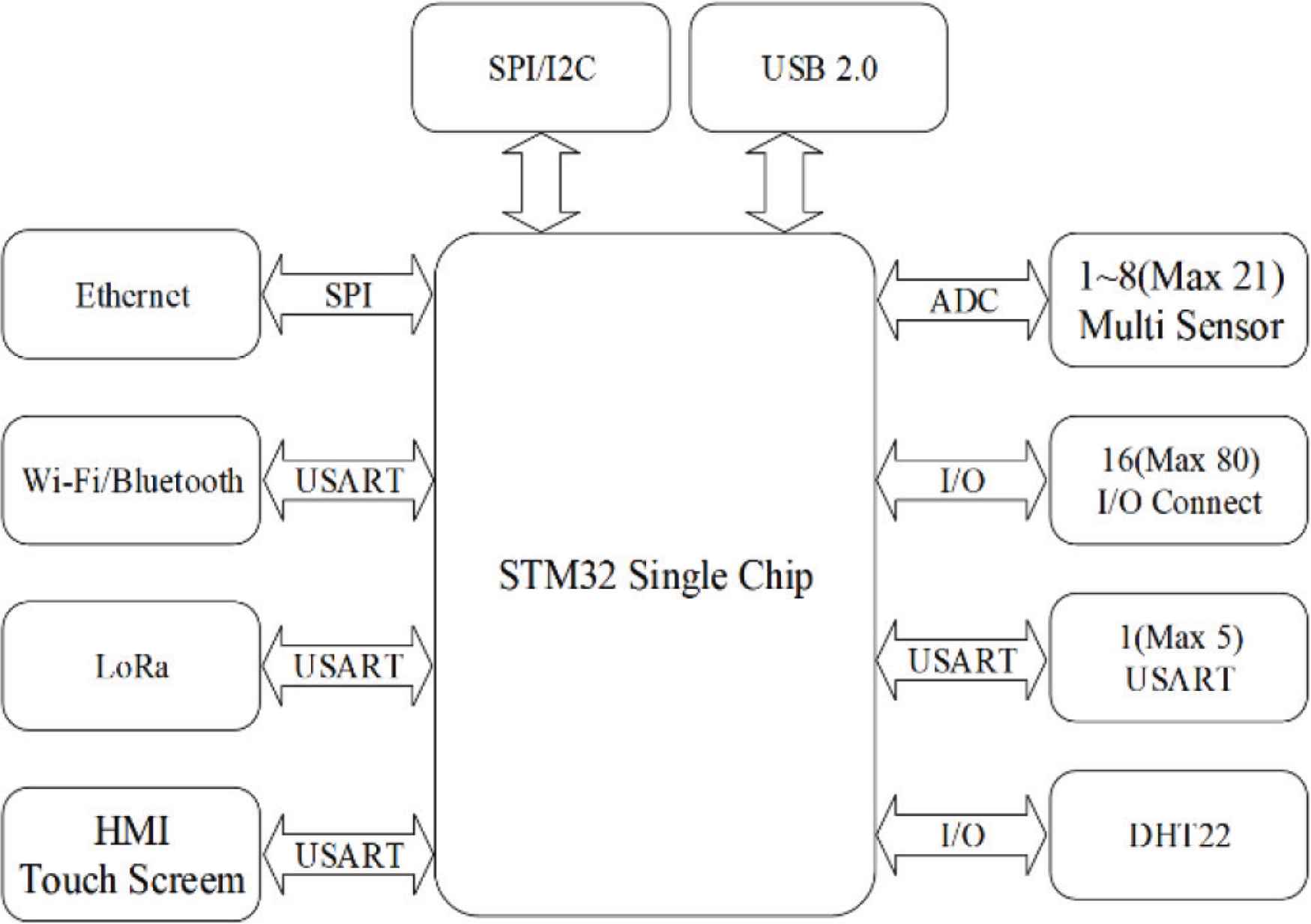
The block diagram of IoT module.
3. ALGORITHMS
In this paper, we use fuzzy-AHP algorithm and AFM to analyze and judge sensor data. We use fuzzy-AHP for sensor data processing and decision making, then use AFM to analyze these data and decision results. In this way, the false positive rate of IoT module or sensor can be obtained, and the analysis result of these false positive rates is used as one of the weights in the fuzzy-AHP processing. This processing can reduce misjudgment rate of IoT module or sensor, and early detection of possible faulty IoT modules or sensors allows each IoT module to be more accurate and intelligent. Because each module may have a different number of sensors, or even different types of sensors, there are three processing methods in fuzzy-AHP.
3.1. Use a Single Sensor
This is the most common and cheapest mode. Since it only has one sensor, it is easy to cause wrong event messages due to sensor problems. In order to reduce the probability of sensor errors, we continuously read the sensor data, the number of readings is j. We set a threshold has the judgment of sensor data. Therefore, we can get S after comparing the measured value v of the sensor with the threshold value which is shown in following equations:
Because there is only one sensor to do multiple sampling, the result is one-dimensional array, so whether or not an event occurs can be evaluated using Equations (2)–(7). We add the values of 1 in the array and divide by the number of samples. For this calculation, we define a fuzzy-logic to determine the severity of the event.
Define E as the influence of sensor on detection event. For example, we can define E = 1–5 to represent the severity of the event as the corresponding degrees normal, possible, warning, danger, emergency, and probability. Then we can define the judgment formula as shown in Equation (4), we can find out the degree or correlation of the sensor’s influence on the event.
3.2. Use Multiple Identical Sensors
This is an advanced usage model to avoid event misjudgments. We set i as the number of sensors, j as the number of samples, h as the threshold value, v as the measurement value of the sensor, and w as the weight value. This weight value is used to evaluate whether the sensor is normal. The default value is 1, and the weight value is automatically adjusted through AFM. Next, we will explain how to process and judge sensor data. If the sensor measurement value is less than or equal to the product of the threshold value and the weight value, Si = 0; if sensor measurement value v is greater than the product of the threshold value and the weight value, Si = 1. We can read multiple data for each sensor, and the number of readings can be set. So, we can rewrite Equation (1) as below:
After collating all comparison results, the following results can be obtained.
Then we add 1 in each column of above formula which is the following equation.
Then we can get.
Similarly, we divide each value in Equation (11) by the number of measurements.
Then bring the result of Equation (12) into Equation (4), use the following equation to confirm whether the event occurred.
This method can avoid erroneous event messages, but it will cause higher costs and more calculations.
3.3. Use Multiple Different Sensors
This method can judge and distinguish events more detailed through the sensing characteristics of different sensors. For example, to detect a flame, an ultraviolet sensor, an infrared sensor, a smoke sensor, and a temperature sensor can be used. Because above sensors can detect some of the characteristics of a fire when a fire occurs, but it may not be able to clearly confirm the occurrence of a fire. Therefore, the use of many different sensors can alert the fire event in advance and clearly indicate the status of the fire.
Similar to previous method of using multiple identical sensors, we set i as the number of sensors, j as the number of samples, h as the threshold, v is the measurement value of the sensor, and w is the weight value. We explained how to process and judge the sensor data. If the sensor measurement value is less than or equal to the product of the threshold value and the weight value, then Si = 0; if sensor measurement value v is greater than the product of the threshold value and the weight value, Si = 1. We can read data multiple times for each sensor, and the number of reads can be set. Therefore, read value of each sensor is compared with threshold value, we can rewrite Equation (1) as follows:
Then substitute the result of Equation (16) into Equations (9)–(12). Because different sensors are used, we can confirm the occurrence of event and also distinguish the status of the event. The judgment formula used here is Equation (4). For example, when we use four kinds of sensors: ultraviolet, infrared, smoke, and temperature, the E of the sensor is “ultraviolet E = 3, infrared E = 2, smoke E = 4, temperature E = 3”. Since each sensor has different relationship to fire, we can define a weight g for each sensor. This weight can be set by user, then we can get the fuzzy evaluation equation as the following:
By using fuzzy evaluation equation, we can know how likely a fire is. As above example, we can describe the event as “a fire may occur, and there is already smoke, so we must pay attention to the temperature”. This can accurately describe the event situation, and provide event handling methods or as a reference for escape decision. We use fuzzy-AHP on the module to reduce the false positive rate of the sensor, and use AFM to adjust the weight value. This algorithm is very suitable for digital detection signals. The sensor data in IoT module is digital data after being processed by fuzzy-AHP, so it can be analyzed by using AFM. The detailed derivation of the equation is detailed in the reference [7,8]. The structure of the entire system is shown in Figure 2.
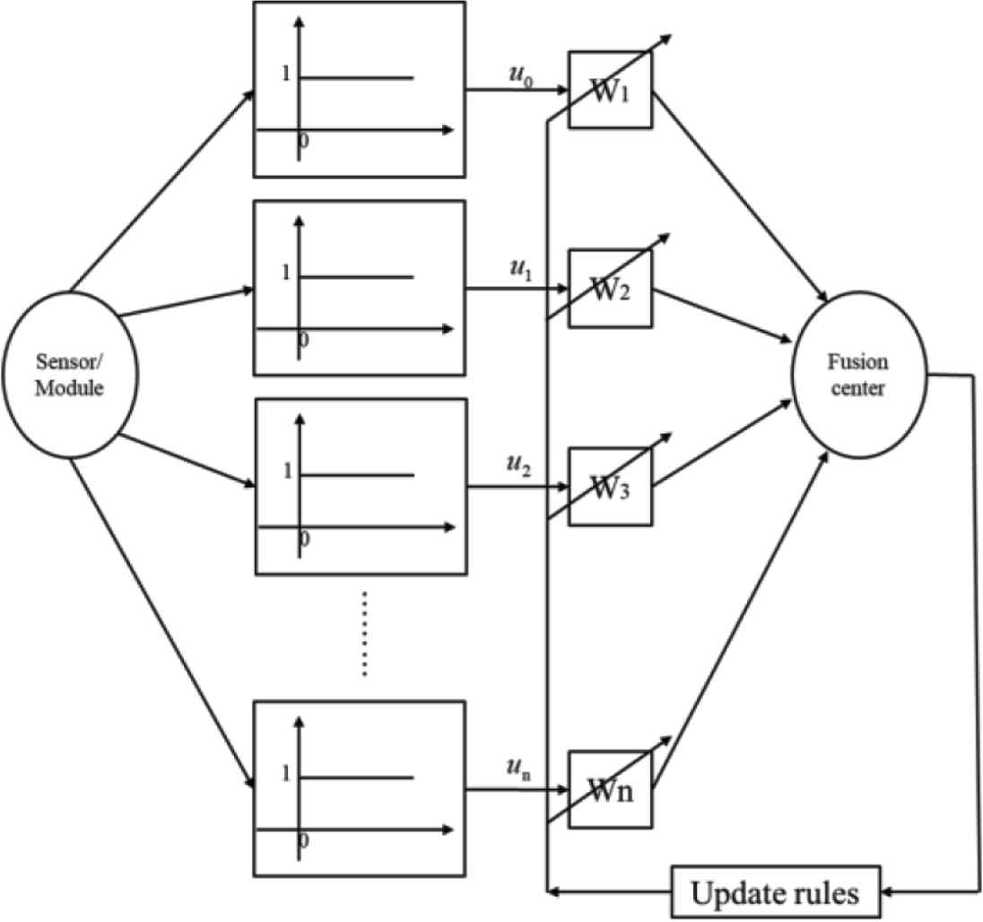
Fusion architecture.
4. EXPERIMENTAL RESULTS
After completing the design of entire IoT module and the derivation of algorithm, we completed actual IoT module. The actual completed module is shown in Figure 3. Figure 3a is the circuit board of IoT module, and 3b is finished product after adding touched LCD. Users only need to connect the power.
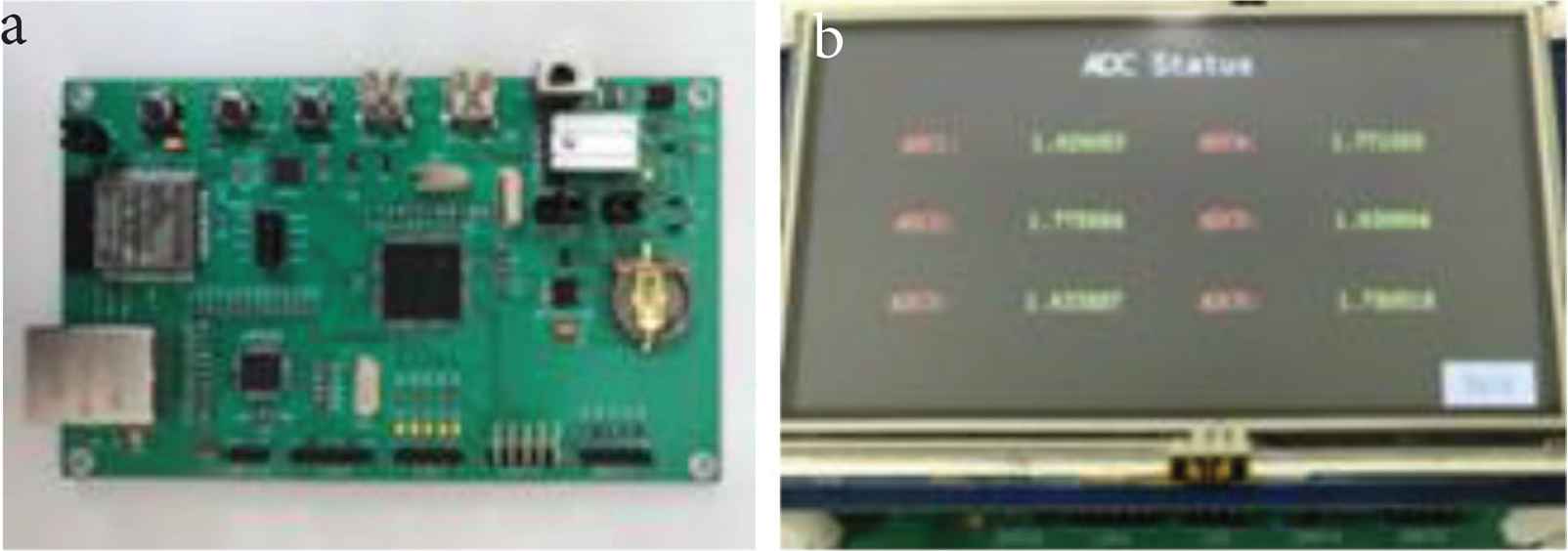
IoT module. (a) IoT module main board. (b) IoT module with LCD.
In addition, we have developed an IoT human–machine interface software, which allows users to quickly build their own application systems. This software is shown in Figure 4. The software is divided into six blocks, and the functions of these six blocks are:
- (A)
Map area: Users can set the map by themselves, and put the I/O or A/D icon of the IoT module onto the map by drag and drop.
- (B)
Setting area: This block can be used to manually operate the IoT module, or to set related I/O or A/D parameters.
- (C)
Connection area: This area will display the connected IoT modules.
- (D)
Function area: This area will show which I/O or A/D of the selected IoT module has not been mapped to the map. And can be used to set the I/O mode to be input or output.
- (E)
Scanning area: the user can select the IP range of the IoT module to be scanned in this area, and which communication interface is used.
- (F)
Attribute area: This area can be used to display or set the I/O or A/D attributes of the IoT module.
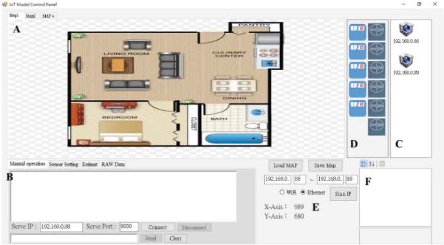
IoT human–machine interface software.
When the user drags and drops the I/O or A/D icon of the connected IoT module to the map area, the system will automatically fill in the relevant data in the “Sensor Setting” page of area B, as shown in Figure 5. Users can edit or set related parameters in this table, and these parameters will be stored in the database.
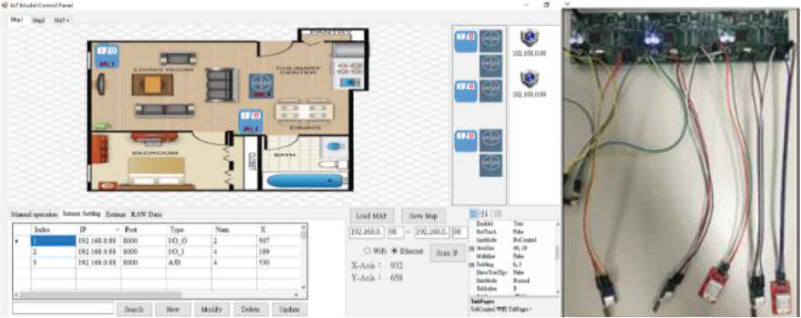
IoT Module and human–machine interface software-sensor setting page.
If the user moves the mouse cursor to the IoT module icon on the map. The system will display as which IoT module this icon is connected to, related data, and the real-time status of the IoT module. As shown in Figure 6a, this icon is connected to the second I/O of 192.168.0.88. The function is output. The current status is “1”, that is, “Open”. If “0” is displayed, it is “Close”. Figure 6b the current icon is the fourth I/O connected to 192.168.0.88, and the communication port is 8000. The function is input. The current status is “2” which means input “0”. If it is input “1”, it will display “3”. Figure 6c is the fourth A/D connected to 192.168.0.88. The current measurement value is “0.5862V”.
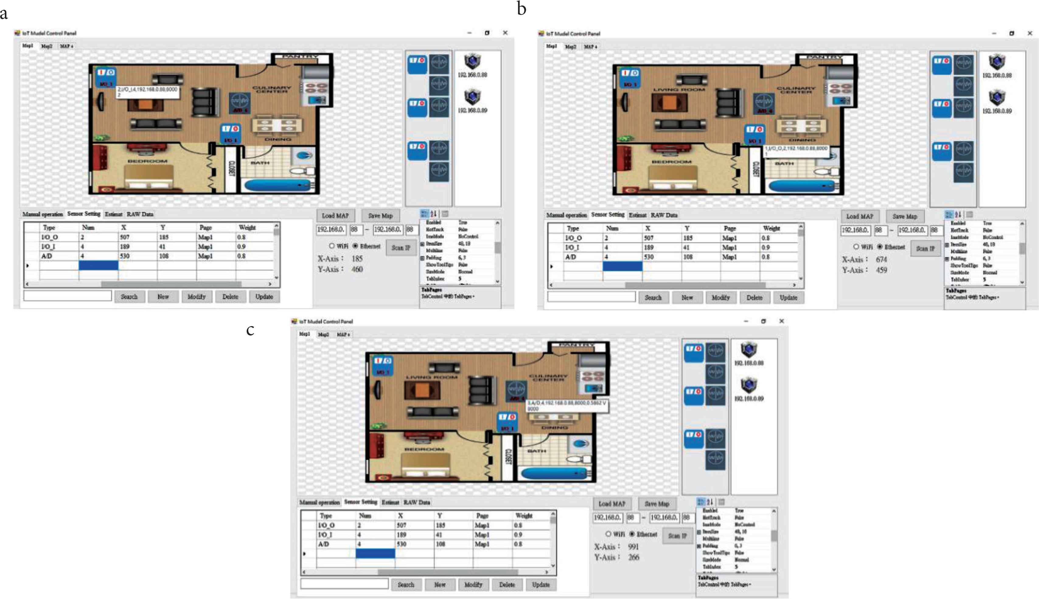
Experimental results, IoT HMI software-Icon Status. (a) IoT HMI software-Icon Status 1. (b) IoT HMI software-Icon Status 2. (c) IoT HMI software-Icon Status 3.
Finally, we used three IoT modules which were connected to sensors to verify Fuzzy-AHP and AFM for analysis. As shown in Figures 5 and 6, the overall test results were good.
5. CONCLUSION
We use a 32-bit STM-32 single chip to design IoT module which can connect many sensors and control I/O. In addition, we use fuzzy-AHP algorithm and AFM to process sensor’s data or IoT module. Using these two methods allows IoT modules confirm events and make decisions. IoT module also can learn and adjust the weight itself or the sensor, so it would be more intelligent. In the future, we will continue to develop various sensor modules and related Web base control systems, so this system can be applied in various fields.
CONFLICTS OF INTEREST
The authors declare they have no conflicts of interest.
AUTHORS INTRODUCTION
Dr. Jr. Hung Guo
 He is an Associate Professor at the Department of National Yunlin University of Science & Technology, Douliou, Taiwan. He received his PhD Degree from National Yunlin University of Science & Technology, Taiwan in 2012. His research interests include sensor network, intelligent systems, and intelligent robot. and technical and vocational education.
Prof. Evgeni Magid
 He is currently working as a Head of Intelligent Robotics Department and a founder, a Professor and the Head of Intelligent Robotic Systems Laboratory at Kazan Federal University. He received his PhD Degree from University of Tsukuba, Japan in 2011. His research interests include fuzzy systems, intelligent systems, and technical and vocational education.
Dr. Kuo-Hsien Hsia
 He is an Associate Professor at the Department of National Yunlin University of Science & Technology, Douliou, Taiwan. He received his PhD Degree from National Sun Yat-Sen University, Taiwan in 1994. His research interests include fuzzy systems, intelligent systems, and technical and vocational education.
Prof. Kuo-Lan Su
 He is an Professor at the Department of National Yunlin University of Science & Technology, Douliou, Taiwan. He received his PhD Degree from National Chung Cheng University, Taiwan. His research interests include robot, intelligent systems, and technical and vocational education.
REFERENCES
Cite this article
TY  - JOUR
AU  - Hung Guo
AU  - Evgeni Magid
AU  - Kuo-Hsien Hsia
AU  - Kuo-Lan Su
PY  - 2020
DA  - 2020/12/31
TI  - Development of IoT Module with AI Function Using STM32 Chip
JO  - Journal of Robotics, Networking and Artificial Life
SP  - 253
EP  - 257
VL  - 7
IS  - 4
SN  - 2352-6386
UR  - https://doi.org/10.2991/jrnal.k.201215.009
DO  - 10.2991/jrnal.k.201215.009
ID  - Guo2020
ER  -