
Simulation of SPWM Fed Three-phase Induction Motor Drive Mathematical Model Using MATLAB Simulink
- DOI
- 10.2991/jrnal.k.200909.006How to use a DOI?
- Keywords
- Three-phase induction motor; DQ-model; voltage source inverter; SPWM
- Abstract
Three-phase induction motors are used in a vast area of applications mainly due to their simplicity, ruggedness and high reliability. With recent advancement in semiconductor technologies, the use of fixed speed induction motor drive is becoming obsolete, majority of the applications now requires inverter-based drives for variable speed operation. In the study of induction motor drive operation, mathematical models are often used to simulate the steady state and transient behavior of induction motor. However, developing such models are not as simple. One must develop the understanding of the mathematical equations to be used and also having the knowledge to solve the equations with the use of computer simulation software. To address this issue, this work presents an approach to implement the mathematical model of a Sinusoidal Pulse Width Modulation (SPWM) fed three-phase induction motor drive in MATLAB Simulink. The sub models include induction motor direct quadrature-model and a voltage source inverter fed by SPWM signal generator. The presented model implementation is able to simulate the dynamic behavior of an induction motor operation, this mathematical model implementation would be useful for further studies on the development of induction motor drive system.
- Copyright
- © 2020 The Authors. Published by Atlantis Press B.V.
- Open Access
- This is an open access article distributed under the CC BY-NC 4.0 license (http://creativecommons.org/licenses/by-nc/4.0/).
1. INTRODUCTION
Recent advancement in semiconductor technologies have further extended the capability of induction motors from the traditional fixed speed to the modern variable speed operation with the use of Pulse Width Modulation (PWM) fed inverter-based drives. Some of the applications include industrial pumps, crane lifters, drilling machines, traction applications such as in electric vehicles, and many others. Developing elaborate models have now become crucial in the designing process of induction motor drive system as the application complexity increases. The model should be able to predict and simulate operational characteristics and performances which would be useful to validate the design process and minimize designing error [1]. However, building such model is not a straight forward task, knowledge of the machine basic electric, magnetic, and mechanical behaviors and also some experience in using computer simulation software are required.
Several available literatures have published their respective induction motor mathematical model implementation approach. Some of the works suggest the use of Simulink’s-function [1,2], others use Simulink’s mathematic operation blocks [3,4], and there are also works that have proposed a solution to avoid MATLAB/Simulink [5] where the motor are modeled completely using C++ programming language. Their works however does not focused on modeling of the Sinusoidal PWM (SPWM) signal and the inverter equations. This paper chooses SPWM control method because it is one simplest. With this, a better understanding on the fundamentals can be developed without the need to dive into the other complex control method. The overview of the equations needed to mathematically model an induction motor drive and the approach to implement them in computer simulation software specifically using MATLAB Simulink are presented here. Three main components of the induction motor drive system are included in this work which are the induction motor DQ-model, the three-phase voltage source inverter [6], and the SPWM signal generator for Voltage Source Inverter (VSI) switching [7,8].
The model be entirely built by writing MATLAB programming code from ground up, or one can use Simulink which provides a better system representation in block diagram form as an alternative. The main advantage of Simulink is that it uses functional blocks instead of programming code.
2. MODEL IMPLEMENTATION
The model describe in this work include the Induction motor Direct Quadrature (DQ)-model, the SPWM model, and the voltage source inverter model. Each of the sub model is presented as follows.
2.1. Induction Motor Direct Quadrature-Model
This is the very first step of modeling an induction motor, it involves reference frame transformation of the three-phase supply (Vas, Vbs, Vcs) voltage into two-phase voltage [9,10]. To simplify later implementation in Simulink, it is convenient to first transform the three-phase voltage using Eq. (1) into a two-phase voltage in stationary reference frame (Vds, Vqs), then from the stationary reference frame to the arbitrary reference frame using Eq. (2).
The DQ model can be then be calculated once vds and vqs are obtained. Implementations of the DQ-model are divided into three parts as follows.
2.1.1. Flux linkages
The first set of equations to be solve part is on the flux linkage as defined in Eqs. (3)–(6):
ωb : Motor angular base frequency
ωe : Electrical supply angular frequency
ωr : Rotor angular frequency (rad/s)
vqs, vds : Stator voltages (V) of q and d-axis
vqr, vdr : Rotor voltages (V) of q and d-axis
2.1.2. Magnetizing flux
The second part calculates the magnetizing flux with the equation shown by Eqs. (7) and (8):
From there, the stator and rotor current (A) in the arbitrary reference frame can be solved as follows.
iqs, ids : stator current (A) of quadrature and direct axis
xls : leakage reactance (Ω) of stator
Fqs, Fds : stator flux linkage (Wb-t) of quadrature and direct axis
2.1.3. Electromagnetic torque and rotor speed
The final set of equations calculate the electromagnetic torque Te (Nm) and rotor speed ωr (rad/s) outputs as shown in Eqs. (12) and (13).
where p is the number of poles, J (Kg/m2) is the moment of inertia and Tl (Nm) is the input load torque.
2.2. Sinusoidal Pulse Width Modulation
Three-phase VSI is typically made up of six power switches that requires proper switching sequence to transform the DC voltage supply into a variable frequency three-phase PWM voltage output. As mentioned, the SPWM is used in this work. To model the three-phase SPWM switching signals, three sinusoidal reference signals which are set 120° phase apart from each other; Vref_n where n represents the three phase a, b, c, the signals are then compared with a high frequency triangular signal VT. The changing of the reference signal frequency fref changes the inverter frequency which then changes the speed of the induction motor [11]. Hence, this relation provides a simple control over the speed of induction motor. However, to produce the varying frequency reference signal, the standard sine function as shown in Eq. (14) is not applicable.
Since the sin function takes argument of angles, simply changing fref by time will not produce a smooth frequency transition, jitter will be seen in the output as the results of jumping phase from one point of the waveform. To solve this issue, the use of phase accumulator is proposed with the Eq. (15) described below:
The phase accumulator can be built using the Backward Euler Method with Eq. (16) and modeled using Simulink’s User-Defined Function block.
The fref can now be varied as intended, even in discontinuous ways, the phase will still change smoothly by time, producing a continuous variable frequency sinusoid.
2.3. Voltage Source Inverter
One way of modeling a three-phase inverter is described by Bose in his book [6] based on the relation of phase voltages and pole voltages as in Eqs. (17)–(19).
van, vbn, vcn : Phase voltages
vao, vbo, vco : Pole voltages
With the voltage source inverter mathematical model is implemented, all the components required are completed and simulation can be run.
To validate the mathematical model implementation, the results of the model described in Section 2 is compared with the Simulink’s preset asynchronous machine drive which is already built and made available by MATLAB in its Simulink library. During simulation, both the mathematical and the Simulink’s preset model use the same 5 Hp motor with parameters as shown in Table 1.
| Parameter | Abbreviation | Value | Unit |
|---|---|---|---|
| Rotor resistance | Rr | 1.083 | Ohm |
| Stator resistance | Rs | 1.115 | Ohm |
| Rotor inductance | Lr | 5.974E-03 | Henry (H) |
| Stator inductance | Ls | 5.974E-03 | Henry (H) |
| Magnetizing inductance | Lm | 0.2037 | Henry (H) |
| No. of poles | P | 4 | |
| Moment of inertia | J | 0.02 | kg/m2 |
Induction motor parameter for mathematical modeling
The results of both models output are presented in the next section.
3. RESULTS
The induction rotor speed, phase current, and electromagnetic torque response are as presented in Figure 1 showing side-by-side comparison of the mathematical model and the Simulink’s preset model outputs with the applied load torque profile.
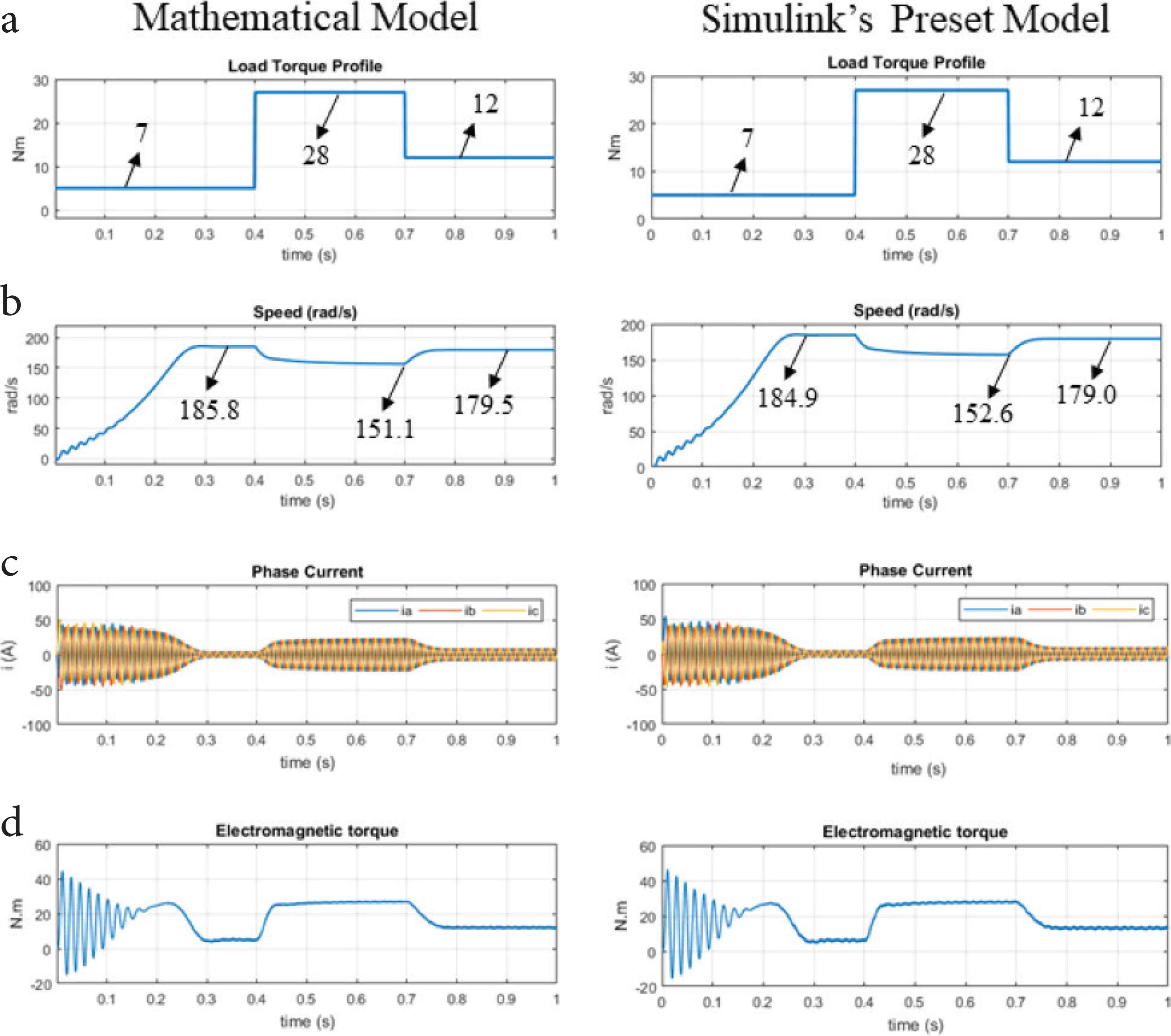
Side by side Mathematical and Simulink’s preset model comparison of (a) load torque applied, (b) rotor speed, (c) phase currents, (d) electromagnetic torque.
From the results shown, the mathematical model and the Simulink’s preset model yield similar response behavior. During starting, transient conditions are observed before the motors got into a steady state condition at time 0.3 s. When the load torque is increased from 7 to 28 Nm, both the model responds with decrease in rotor speed, increase in phase currents amplitude, and increase electromagnetic torque, transient region can also be observed whenever load torque change occurred before getting back into steady state condition.
4. CONCLUSION
This work has presented an approach to implement an SPWM fed three-phase induction motor drive. The model was built in Simulink entirely based on the equations described in Section 2. The implementation process is also presented in a step-by-step approach so that the work can be easily followed. The results produced by this model have shown similar behavior to that of Simulink’s preset induction motor drive model, which validates that the mathematical model implementation is working as expected. This model implementation would be useful for future development of induction motor drive systems.
NOTE
The complete Simulink model implementation described in this paper can be referred at MATLAB Central File Exchange: https://www.mathworks.com/matlabcentral/fileexchange/73260-dq-model-of-3-phase-induction-motor-drive.
CONFLICTS OF INTEREST
The authors declare they have no conflicts of interest.
AUTHORS INTRODUCTION
Mr. Amir Rasyadan
 He received Master of Engineering Technology degree from University of Kuala Lumpur in 2019. His research interests include industrial automation, digital signal processing, and power electronics.
Dr. Pranesh Krishnan
 He is currently serving as a Post-Doctoral Researcher at Malaysian Spanish Institute, Universiti Kuala Lumpur, Kulim, Malaysia. He completed his Masters (Mechatronics) and PhD (Mechanical) from Universiti Malaysia Perlis, Malaysia. He obtained his Bachelors (Information Technology) degree from Anna University, India. He is a member of IEEE, and a Graduate Technologist from MBOT. His research interests include Signal Processing, Driver Drowsiness and Machine Learning.
Prof. Dr. Sazali Yaacob
 He completed his PhD and MS degrees from the University of Southampton and the University of Surrey, United Kingdom respectively. He has published over 300 articles in conferences and journals. He is a life member of Institute of Engineers and recipient of a number of awards.
Dr. Mohamed Rizon
 He graduated Doctor of Engineering at Department of Computer Science and Intelligence System in Oita University, Japan. He was a Professor of Biomedical Technology in King Saud University, Saudi Arabia in 2010. He served at MIEC, Fuzhou University, China in 2019. Currently, he is a Professor at Department of Electrical and Electronics, UCSI University, Malaysia.
Dr. Chun Kit Ang
 He received his Bachelor of Engineering Degree with First Class Honors in Mechatronic Engineering from University of UCSI, Malaysia in year 2010. In end of year 2010, he was attached with Universiti Putra Malaysia for his PhD in Mechanical and Manufacturing Engineering and graduated in year 2014. Currently, he is the Dean for Faculty of Engineering Technology and Built Environment, UCSI University. He is interested in artificial intelligence, soft computing, robotics, and mechatronics. He has published many papers which related to the application of Artificial Intelligence in recent years.
REFERENCES
Cite this article
TY  - JOUR
AU  - Amir Rasyadan
AU  - Sazali bin Yaacob
AU  - Pranesh Krishnan
AU  - Mohamed Rizon
AU  - Chun Kit Ang
PY  - 2020
DA  - 2020/09/14
TI  - Simulation of SPWM Fed Three-phase Induction Motor Drive Mathematical Model Using MATLAB Simulink
JO  - Journal of Robotics, Networking and Artificial Life
SP  - 170
EP  - 174
VL  - 7
IS  - 3
SN  - 2352-6386
UR  - https://doi.org/10.2991/jrnal.k.200909.006
DO  - 10.2991/jrnal.k.200909.006
ID  - Rasyadan2020
ER  -