
Link Failure Tolerant GPSR Protocol
- DOI
- 10.2991/ijndc.k.210628.001How to use a DOI?
- Keywords
- VANET; GPSR; link failure; predictive position; threshold
- Abstract
Link failure cause packet loss, increased delays, disconnection from the network or even the shutdown of the inter-vehicle communication system vehicle-to-vehicle. Routing protocols suffer from this situation due to the lack of fault tolerance mechanisms that are intended to make the vehicular ad hoc network capable of remaining functional over time with low response time and/or high throughput; despite failures. Through this paper, we propose a version of the Greedy Perimeter Stateless Routing (GPSR) protocol that is tolerant to link failures based on the prediction of the future position of each vehicle (position prediction-GPSR) and a minimum threshold of the vehicle coverage area (position predictive with threshold-GPSR) to elect the next hops. Simulation results show that the proposed approach offers good performance.
- Copyright
- © 2021 The Authors. Published by Atlantis Press B.V.
- Open Access
- This is an open access article distributed under the CC BY-NC 4.0 license (http://creativecommons.org/licenses/by-nc/4.0/).
1. INTRODUCTION
With the rapid development of wireless communication technologies, the Vehicular Ad Hoc Network (VANET) is a fascinating topic for many researchers. Based on the IEEE 802.11p wireless radio interface, VANET includes Vehicle-to-Vehicle (V2V) and/or Vehicle-to-Infrastructure (V2I) communications. It can provide a basis not only for improving road safety, but also for driver assistance, entertainment and comfort services for vehicle users during their journey. In recent years, many projects have been developed on VANET. However, due to the high mobility of the node resulting in a rapidly changing topology, there are still some challenges for the achievement of VANET, notably, the frequent disconnection of the network and link failure, which leads to significant packet loss and increases end-to-end delays. To this effect, the implementation of an efficient routing protocol is necessary to overcome the problems related to link failure on VANET.
A number of VANET routing protocols have been proposed and evaluated to date. These are mainly Topology Based Routing Protocols (TBR) and Position Based Routing Protocols (PBR). TBR protocols generally use a proactive or reactive approach to establish routes. Proactive routing protocols, such as Optimized Link State Routing (OLSR), must periodically update and maintain routing tables for all nodes on an ongoing basis. Whereas, reactive routing protocols such as Ad-Hoc Demand Distance Vector Routing (AODV) creates routes only when packets need to be sent and maintains routing tables for the nodes participating in the routing during this communication. In contrast, PBR protocols do not establish routing tables or storage routes.
They are based on the selection of the next potential hop, taking into account the position information of neighboring nodes and Hu et al. [1].
Several VANET performance studies have shown that PBR protocols are more efficient. Notably, the Greedy Perimeter Stateless Routing (GPSR) protocol, a popular PBR protocol, innovative and in full expansion which has been studied several times for possible improvement under the aegis of a metric (life time, buffer length, multi-hop...), it is also adapted to a highly dynamic vehicular environment due to its better packet delivery rate and its low transmission delay. Our work is a proposal of a link failure tolerant solution based on a preventive strategy that guarantees the selection of the best next hop, applied on the GPSR protocol. The rest of this paper is organized as follows. In the next section, we present the related works. Section 3 states our motivation. Section 4 describes our approach with an overview of our architecture and its implementation. Section 5 is dedicated to experimentation and discussion of the results. Finally, we close the document and highlight a perspective in Section 6.
2. RELATED WORKS
In the hope of making the VANET network able to remain operational in spite of interruptions caused by network layer failures, a non-exhaustive panel of solutions applied to the GPSR routing protocol has emerged through the academic world, the most widespread of which are:
To remedy the failure to update the information embedded in the GPSR packet header when the neighboring node acquires a new position caused packet loss, Rao et al. [2] propose a GPSR protocol based on lifetime calculation (GPSR-L). The approach aims to keep nodes whose lifetime timer has not expired despite the expiration of the HELLO timer in the neighbor list by each node. This results in efficient next hop selection, thus avoiding packet loss in highly mobile environments.
From the experiments performed on the GPSR-L, the authors state that the results obtained are better than those of GPSR; not only the packet delivery rate is increasing by 20–40%, and there is also a significant improvement in the packet delivery ratio for different Hello message intervals compared to GPSR. However, the lifetime calculation proposed in this model was provided under six simple scenarios.
Hu et al. [3] propose an Enhanced GPSR Routing Protocol (E-GPSR) based on the available length of the node buffer mitigating the congestion problem in the VANET network caused by multiple broadcast nodes successively transmitting data to the same relay node. E-GPSR takes into account not only the distance between the next hop and the destination node but also the available buffer length of the next hop. This reduces routing delay and packet loss caused by waiting longer than the retransmission delay. The results of the analysis show that the enhanced E-GPSR protocol in the vehicle environment has a lower packet loss rate and less transmission delay than traditional GPSR.
To reduce link failure and transmission failures due to high mobility and rapid change of topology, Hu et al. [1] propose an improved GPSR protocol based on a Neighborhood Table Update Strategy. The authors modify the Hello Packet to specify the selection of vehicles neighboring a hop in the transmission range of the current node. So they add the fields: speed, direction of vehicle movement, priority flag and density. As a result, the transmitter has enough information not only to predict the future location of its neighbors and store it in its neighborhood table, but also to estimate the number of neighboring vehicles in its transmission range. The selection of the next hop is based on the notion of established priority.
Purohit et al. [4] propose an Enhanced GPSR Routing Protocol (MGPSR); based on a multipath technique aimed at bypassing the frequent disconnection of the designed single path between source and destination, better manage congestion and improve quality of service. The MGPSR transmission process consists of adopting the GPSR perimeter transmission phase as such and reformulating the greedy forwarding phase establishing two paths instead of a single path between source and destination. This path construction is done in the same way as that of Ad-hoc On-demand Multipath Distance Vector (AOMDV) but the latter maintains several paths, However, MGPSR will define only one alternate path between each source and destination pair.
To improve the efficiency of the GPSR geographic routing protocol, Katsaros et al. [5] propose a routing strategy based on multi-layer position weighted routing (CLWPR). The proposed algorithm uses information on the quality of the link layer in terms of frame error rate, SNIR and MAC and positioning from navigation to anticipate the characteristics of an urban environment.
In the same context, Bouras et al. [6] present an improved GPSR using weight calculation to select the next best hop. This weight is calculated based on location and speed information, as well as link quality metrics extracted when receiving HELLO.
The advanced GPSR protocol called Advanced Greedy Forwarding (AGF) is designed by Sharef et al. [7]. AGF integrates the direction, the speed of a node in the Hello packet and the total travel time. Thus, depending on the speed vector, and the direction all nodes can filter out obsolete nodes in their neighborhood table. Furthermore, With the total travel time, each transmission node can better establish the divergence from the original position of the destination and get closer to its current position.
Karp [8] has been shown that the cost of planarization, the non-uniform distribution of cars and radio obstacles make the perimeter mode of the GPSR ineffective in urban configurations. To remedy the latter, Lochert et al. [9] propose a new routing approach for mobile ad-hoc networks, called Greedy Perimeter Coordinator Routing (GPCR). It uses the concept of junctions nodes to control the next route segments that packets should follow. The GPCR traverses junctions using a low-power transfer procedure and adjusts the routing path according to the recovery strategy based on the topology of the streets and junctions. However, GPCR has three major drawbacks. First, the junction nodes must be determined, which can lead to protocol overload. Second, the recognition of a junction node, which is defective in a GPCR, is extremely crucial to avoid local peaks and the consequent reduction of hops. Finally, even if the junction node detection algorithm is perfect, the transfer to a node at a junction is often unnecessary and counterproductive.
Lee et al. [10] propose the GPSRJ+ protocol to improve the packet distribution ratio of the GPCR protocol. GPSRJ+ has been suggested as an intuitive predictive design that removes obstacles at an intersection while maintaining map planes. It uses two-hopping Hello messages to visualize the routes that may be occupied by the neighboring junction node. If its prediction shows that the neighboring junction intends to send the packet on a road with a different direction, it sends to the junction node; otherwise, it diverges from the junction and sends the packet to its farthest neighboring node. This means that each node will send a Hello message containing its coordinates in addition to the road segments on which its neighbors are located. One of the strengths of this protocol is that it does not require an expensive planarization scheme because it uses the natural look and feel of urban maps. However, its realistic roads follow a very complex trajectory even though it uses a simple linear trajectory.
Shelly et al. [11] propose a new GPSR routing protocol based on reliability (GPSR-R), it is dedicated in particular to semi-urban environments (highways). It has been designed to bypass the link failure that often leads to significant packet loss. In GPSR-R the selection of the next hop is performed based on link reliability; defined as the probability that a link is active for a limited time. The latter is calculated by the vehicle tagged for each of its neighbors, stored in the neighborhood table and updated periodically. Thus, the proposed protocol ensures that nodes using links with a reliability factor higher than a given threshold are selected when transmitting data and building a route from source to destination.
Squalli Houssaini et al. [12] propose a GPSR protocol based on forecasting (GPSR+PREDICT), This protocol is based on (i) the location of nodes in geographic protocols, (ii) the exploitation of information available in the GPS and not used by the GPSR, and (iii) countering problems encountered such as link failure leading to poor routing decisions. In fact, each node uses its geographical position, speed and direction to estimate its position in the near future. This future position is attached to the Hello packets and recalculated at each sending of the periodic Hello packet.
Menouar et al. [13] propose a new routing concept called MOvement Prediction Routing (MOPR) to improve existing unicast routing protocols, in particular AODV, and make them suitable for VANETs. This concept, based on the prediction of vehicle movement, estimates the stability of each communication link in the network in terms of communication lifetime, then selects the most stable route composed of the most stable intermediate links from the source to the destination.
Menouar et al. [14] propose a new heuristic explaining the application of the MOPR concept on position-based routing protocols, notably GPSR. In this case, during MOPR–GPSR routing, each vehicle wishing to send or transfer data must first estimate the future geographic location after a time t for each neighbor. Then, it selects as the next hop the neighbor closest to the destination that has no future location in its communication area after time T. Indeed, MOPR–GPSR avoids the case where a next hop goes outside the communication range during a data packet transmission.
Silva et al. [15] propose a GPSR protocol with a new transmission strategy called Adaptive GPSR (AGPSR). The latter is based on bypassing the nodes that delivered the packets in recovery mode. AGPSR uses an additional field in the Neighborhood Table (NT): “trusted neighbor status” which is used in the greedy mode routing process. In addition, the right-hand rule of the perimeter mode is replaced by a new recovery algorithm called continuous greedy mode. Indeed, the selection of the next node in greedy mode is based on the minimum distance to the destination and the trusted status.
To select the best path and bypass routing loops, Silva et al. [16] propose a new routing strategy called Path Aware GPSR (PA-GPSR), based on the classical GPSR protocol. PA-GPSR not only improves greedy forwarding by introducing two additional extension tables [Deny Table (DT) and Recently Sent Table (RST)] in the neighbor table, but also perimeter forwarding by replacing it with a new algorithm based on the right- and the left-hand rule. The results attest that the PA-GPSR strategy performs better than the traditional GPSR.
Rodrigues et al. [17] propose a new version of conventional GPSR, named GPSR-with Position Prediction and Uncertainty (GPSR-PPU), dedicated especially for Flying Ad-hoc Network (FANET). This protocol improves the selection of the next node (Drone) by focusing on the prediction of the position of neighboring nodes and the uncertainty of their missions.
Bengag et al. [18] propose two complementary protocols named respectively Density-Velocity-Aware-GPSR (DVA-GPSR) and Enhanced-GPSR (E-GPSR). These two protocols represent an enhanced version of the well-known GPSR protocol. They aim to reduce the link breakage problem commonly encountered in VANET communication. DVA-GPSR and E-GPSR improve the selection of the best next hop based on four metrics: distance, direction of vehicles, velocity variation between the target node and the next hop candidate vehicle, and the neighbors density of the candidate next hop.
3. MOTIVATION
All of the cited approaches are beneficial in the majority of scenarios, but they all base all required calculations potentially on information (fields) added in the Hello package. In addition, most of these approaches propose a radical change in the process of selecting the best hop compared to the original GPSR using more complex calculations.
Namely, in the GPSR protocol, the neighborhood table of a node includes obsolete information about the position of its neighbors. This problem can be solved by increasing the incidence of Hello, but this will generate congestion and cause possible collisions. Also, the destination position in routing packets is never updated, while the destination moves (mobility) while the packet is routed from the source. To achieve this, we propose a simple approach that is tolerant to link failures while maintaining the basic mechanism of the GPSR protocol.
4. PROPOSED APPROACH
In this section, we propose a preventive, fault-tolerant approach to link failures applied to the GPSR geographic routing protocol. This approach is based on the instantaneous prediction of the node’s position for the selection of the nearest potential neighbor, expressed in predictive distance, and its location relative to the threshold in the coverage area. In the following we detail the proposed approach.
4.1. Selection Criteria
Let a node (Ni) among a set of nodes (N) between a source (S) and a destination (D). To select the node (Ni) via its predecessor (Nj) as the next potential hop; (Ni) must meet the following two criteria:
- •
Position: Ni must be within the communication radius of its predecessor in terms of predicted position.
- •
Short distance: Ni must be closest to destination D in terms of predicted distance.
4.2. Next Hop Pre-selection Process
Contrary to basic GPSR, we have integrated a pre-selection procedure that helps to better define the neighborhood for a better decision making of the next potential hop. The pre-selection takes place in three steps.
Step 1: Maintaining Beacon message history
This step consists in keeping track of the penultimate Beacon (instant t−1) for each neighbor Ni. In other words, when a new Beacon (instant t0) is received, we will have for each neighbor Ni [Beacon (t−1) and Beacon (t0)] which will be successively saved in the new neighborhood table (Table 1).
| Identification | Section A | Section B | ||||||||
|---|---|---|---|---|---|---|---|---|---|---|
| Information collected from the beacon received at time t−1 (penultimate beacon packet) and the predictive position calculated at the same time | Information collected from the beacon received at time t0 (last beacon packet) and the predictive position calculated at the same time | |||||||||
| ID neighbor | Geo-coordinates of neighbor | Time stamp | Predictive position of neighbor | Geo-coordinates of neighbor | Time stamp | Predictive position of neighbor | ||||
| @ | TS | TS | ||||||||
New neighborhood table format
Step 2: Predictive position calculation
Each node (Nj) calculates the future position of its moving neighbors.
We define the predictive position by the following formula:
Predictive Position = Initial Position + Displacement
With:
Initial position: retrieved from the received Beacon.
Displacement = [Beacon reception time (t0) − Beacon reception time (t−1)] * Speed.
Speed: It is the instantaneous speed of each node that we calculate according to the known formula V = d/t for each axis as follows:
with t = (t0 − t−1): t = time interval between two Beacons.
We then calculate the predictive position at time t as follows:
Step 3: Comparison to the threshold
In this last step, each node (Nj) is in charge of comparing the predictive positions of these neighbors calculated with a given threshold and to draw from them those that deserve the continuation of the selection process of the next hop.
Then, for each node (Ni) belonging to the communication radius of (Nj).
If the predictive position of (Ni) is lower than the threshold θ which delimits the output of the communication radius of (Nj) in the interval [T0, T0 + ΔT], then it is allowed to start the calculation of the predictive distance between Ni and D for a possible selection of (Ni) as the next hop of (Nj).
At the end of this operation, only the set of pre-selected neighboring vehicles are concerned by the selection process for the next hop.
4.3. Next Hop Selection Process
In the following we describe the process of selecting the next hop in greedy and perimeter modes
• Greedy mode:
Step 1: Calculation of the distance
If the received data packet is marked in Greedy forwarding mode and the address mentioned above does not correspond to that of the current vehicle (Nj), this immediately calculates the future distance between its preselected neighbors and the destination based in particular on the predictive position described above. The predictive distance (DP) is formulated as follows:
DP (Ni) = Position (D) – PP (Ni)
Avec:
Step 2: Choose the next best hop
After calculating the distance (DP) between each neighbor and the destination, node Nj will choose the Node Ni with the minimum distance by selecting it as the next hop.
• Perimeter mode
In perimeter mode, we list the two cases below:
Case 1: when a data packet is transmitted in perimeter forwarding mode it first tries to switch to greedy mode by checking if the distance from the current node to the destination is less than the distance from the point where the packet entered perimeter mode (Lp) to the destination, otherwise it will be transmitted at the first hop that is counterclockwise (application of the so-called right hand rule), until it reaches the destination.
Case 2: when a data packet is transmitted in greedy forwarding mode and the current node fails to transmit this packet in this same mode when faced with a local maximum (i.e. none of its preselected neighbors is close to the destination), the transmission mode immediately switches to perimeter forwarding, hence the application of right-hand rule to reach the next hop.
Moreover, since perimeter forwarding is recursively (alternatively) linked (connected) with greedy forwarding on which we have implemented a pre-selection mechanism and instantaneous prediction of future positions, we have brought to the operation of perimeter forwarding a prediction of the next potential hop at the end of performance in terms of link failure tolerance.
| ∀(Ni) ∈ RC (Nj) |
| if PP(Ni) < θ |
| then Authorize the calculation procedure for DP(Ni) |
| else exclude Ni |
| With |
| Ni: Neighbor Node, i = 1…n |
| PP: Predictive Position of Ni |
| θ: threshold |
| DP(Ni): Distance between node Ni and destination |
Pre-selection of next hops
4.4. Structure of the Packet and Neighbors List
With the approach proposed and applied to GPSR, upon reception of a beacon packet each vehicle stores all the information in its neighbor list. Therefore, current and future position information is available to be used when calculating the next best hop. The illustration of the beacon packets and the neighbor list used in our approach are presented respectively in the Tables 1 and 2.
| ID node | Geo-cordinates of node | Timestamp | Size of paquet | |
|---|---|---|---|---|
| @ | TS | Size | ||
Hello GPSR package format
We maintain the same format of the original GPSR’s Beacon packet to avoid generating additional overheads.
We added: the predictive geographic coordinates field «Xp(t0), Yp(t0)» (time t0) of each neighbouring node, as well as an extension (Section A) conveying the information corresponding to the penultimate received beacon (time t−1) and the future geographic coordinates «Xp(t−1), Yp(t−1)» (time t−1).
| Section A: beacon fields received at time t−1 |
| Section B: beacon fields received at time t0 |
| Nj: emitter vehicle |
| Ni: neighboring vehicle |
| While Nj receive beacon packet do |
| If Ni already exists in neighbors list of Nj |
| then |
| If (Section A = !empty ∧ Section B = !empty) then |
| Overwrite the information in Section A with the information in Section B. |
| Insert the information of the new beacon received in section B |
| Else |
| if (Section B = !empty) then |
| Move the information from Section B to Section A. |
| Insert the information of the new beacon received in Section B |
| Else |
| Insert the information of the new beacon received in Section B |
| End |
| End |
| Else |
| Add as new entry in Section B |
| End |
| End |
Neighborhood table update
This addition allows keeping the history of two received beacon packets from each neighbor, calculating the predictive position, save it in the added fields and updating it at each entry.
4.5. Flow Charts and Algorithms
In what follows we present the algorithm for updating the neighborhood tables and the diagram of the greedy strategy proposed by our approach (Figure 1).
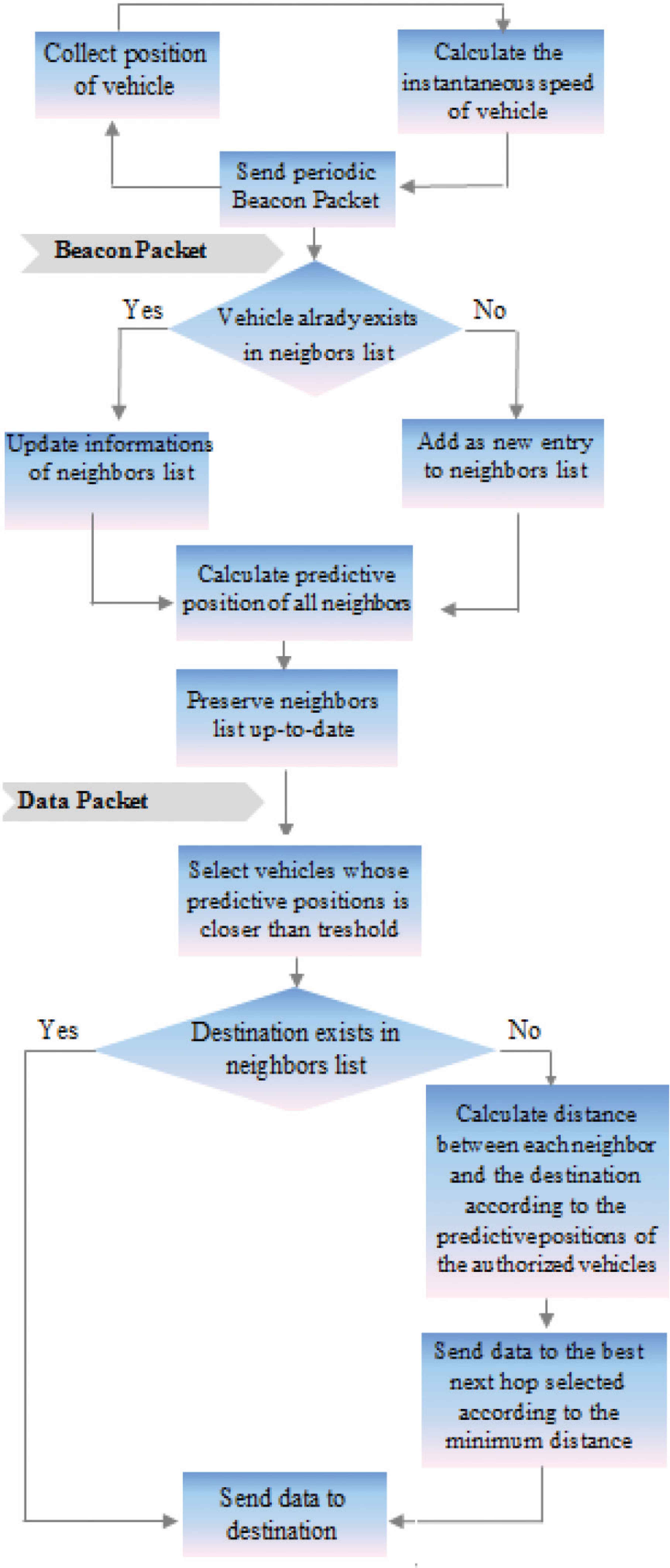
Diagram of the proposed approach.
5. SIMULATION AND RESULTS
First, we implemented the mechanism for predicting the position of neighboring vehicles in the GPSR protocol (which we named PP-GPSR: Position Predictive-GPSR). After that, we introduced the notion of the threshold on the PP-GPSR protocol (which we named PPT-GPSR: Position Predictive with Threshold-GPSR).
Then, to evaluate the performance of proposed protocol called PPT-GPSR, several simulations were established and these results are compared with the conventional GPSR protocol and PP-GPSR protocol. The network simulator NS-2 [19], version 2.34 has been used to conduct simulation experiments.
Also, we used a real city topology which is a part of Malaga, Spain (Figure 2) [20].
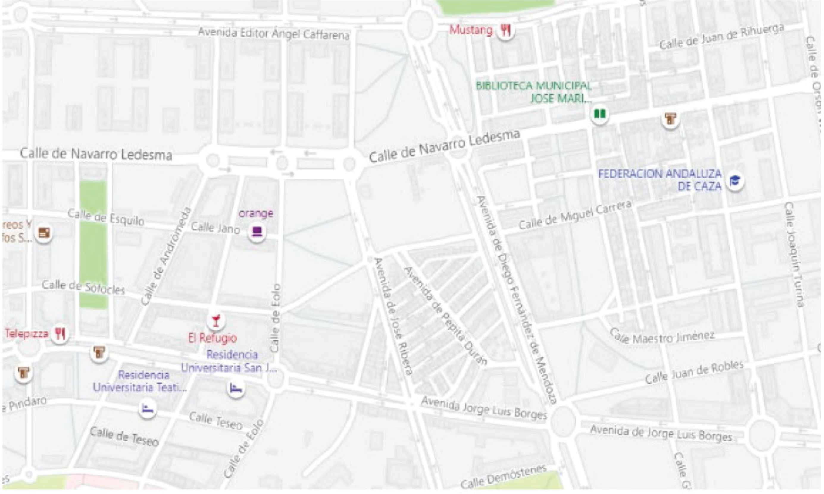
Urban topology: part of Malaga city.
5.1. Performance Metrics
5.1.1. Packet delivery ratio
It is defined as the number of correctly received packets at the destination vehicle over the number of packets sent by the source vehicle. We calculated it with Equation (8)
5.1.2. End-to-end delay
It is defined as the average time in seconds that a data packet takes to be transmitted from the source till the destination vehicle.
It represents the main parameter that must be improved during the evaluation of a routing protocol. A good protocol must have an end-to-end delay average as low as possible. Its calculation is as follows:
5.1.3. Routing overhead
It is defined as the number of byte routing packets generated in the network by the routing protocol on the size of the data packets correctly received at the destination vehicle. We use the following Equation (10) to calculate it
5.1.4. Average path length
It is defined as the average number of hops along the shortest paths for all possible pairs of network nodes. Its calculation is as follows in Equation (11)
5.1.5. Packet loss rate
It represents the ratio between the number of packets lost and the total number of packets sent by the source vehicle. It is calculated as the following equation shows
5.2. Results and Discussion
We performed the simulation of the scenarios according to the GPSR, PP-GPSR and PPT-GPSR protocols. Each simulation is performed with (a) beacon interval = 0.5 s, (b) beacon interval = 3 s and (c) beacon interval = 5 s. The simulation parameters are presented in Table 3.
| Parameter | Value |
|---|---|
| Simulation platform | NS-2 |
| Channel type | Wireless |
| Simulation time (s) | 500 |
| Simulation area | 900 * 1000 m2 |
| Physical layer | Phy/WirelessPhyExt |
| Mac layer | IEEE802_11p/802_11Ext |
| Propagation model | Two-Ray-Ground |
| Traffic model | CBR/UDP |
| Routing protocols | GPSR/PP-GPSR/PPT-GPSR |
| Threshold (m) | 230 |
| Radio range (m) | 250 |
| Beacon period (s) | 0.5, 3, 5 |
| Packet size | 512 octets |
| Speed of vehicle (km/h) | 20–60 |
| Vehicle number | 20, 40, 80, 120, 160 and 200 |
| Number of traffic | 10, 15, 20 and 30 connections |
Simulation parameters
The results below represent the averages of the results obtained. For each scenario based on the number of vehicles (20, 40, 80, 120, 160 and 200 vehicles) 20 then 30 connections are simulated. For each scenario as a function of the number of connections (10, 15, 20 and 30 connections) a density of 120, 160 and then 200 vehicles are simulated.
Figure 3 shows the packet delivery ratio as a function of the number of vehicles. We see that regardless of the value of the beacon interval, the delivery rate varies with the number of vehicles. The average difference in rates varies between 20% and 40% between the three protocols. We constate that the PPT-GPSR protocol prevails over the PP-GPSR protocol, while the GPSR protocol is significantly lower regardless of the density of vehicles.
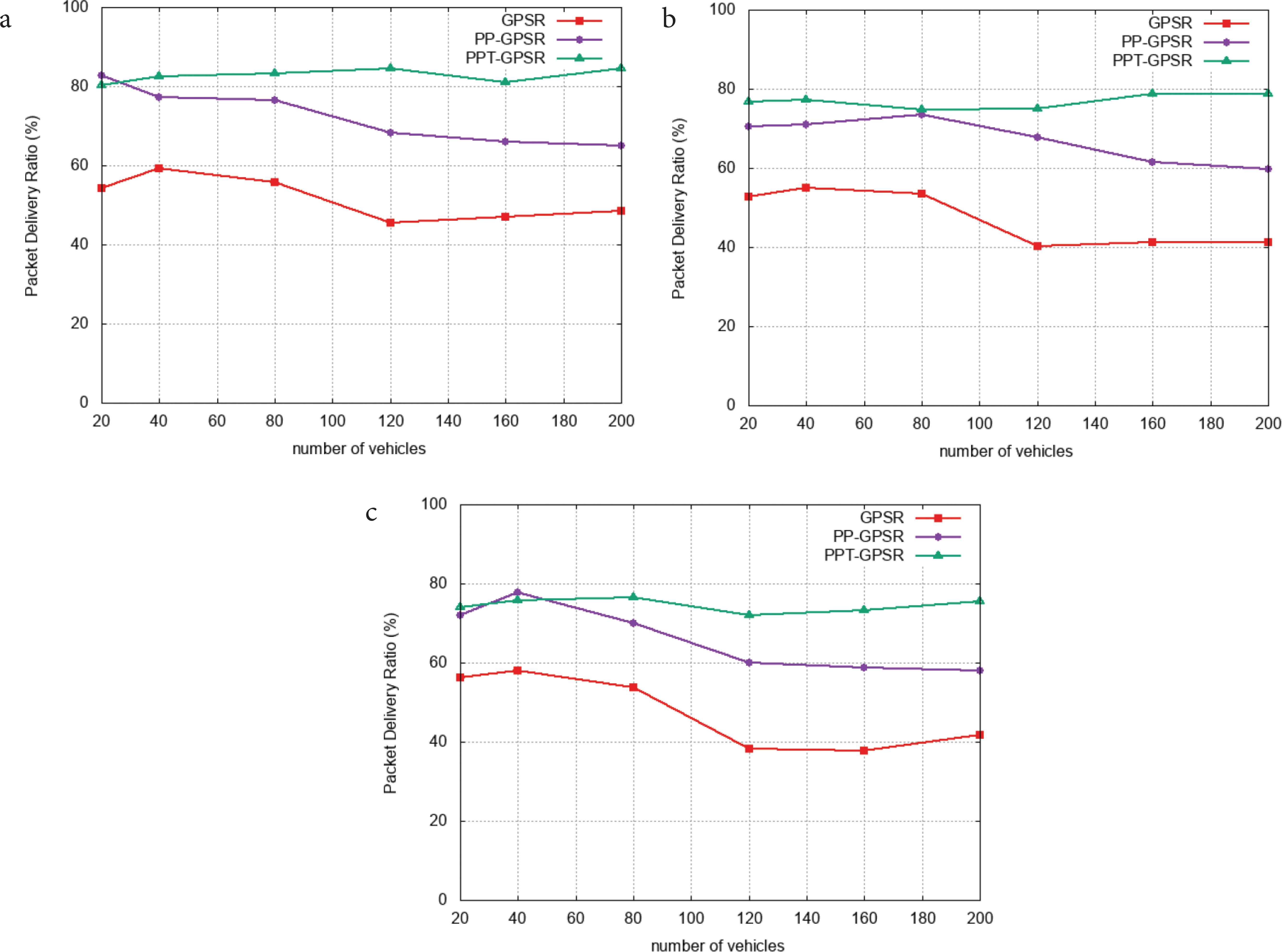
Packet delivery ratio vs. number of vehicles. (a) Beacon interval = 0.5 s. (b) Beacon interval = 3 s. (c) Beacon interval = 5 s.
Figure 4 shows the packet delivery ratio as a function of the number of connections. Similarly, the difference is significant and the PPT-GPSR protocol outweighs the other two.
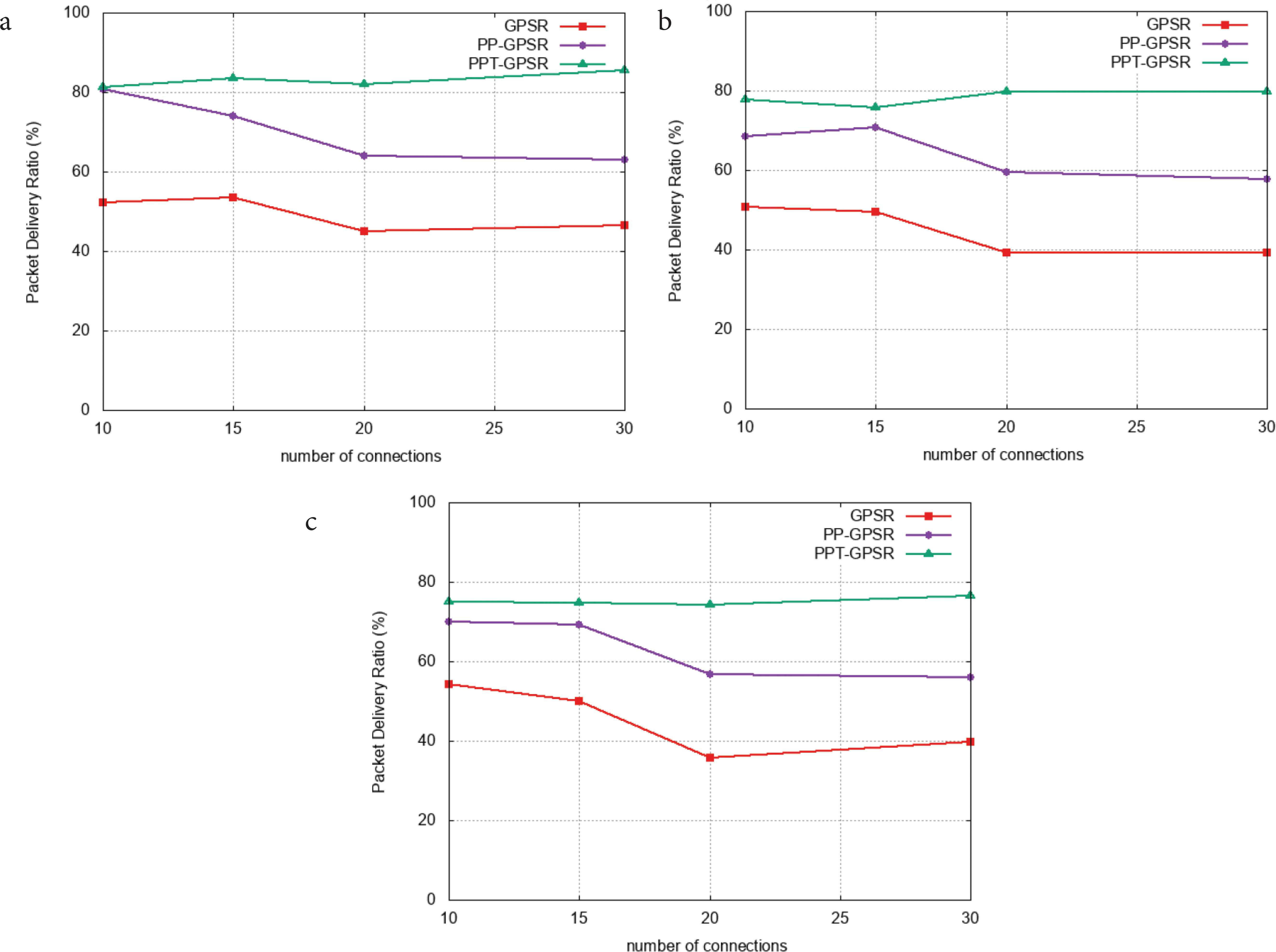
Packet delivery ratio vs. number of connections. (a) Beacon interval = 0.5 s. (b) Beacon interval = 3 s. (c) Beacon interval = 5 s.
The packet loss rate (Figure 5) increases with the number of vehicles, regardless of the value of the beacon interval. The PPT-GPSR solution offers the lowest possible packet loss rates. The difference in rates ranges from 20% to 45% compared to the GPSR loss rates and between 4% and 20% compared to the PP-GPSR loss rates.
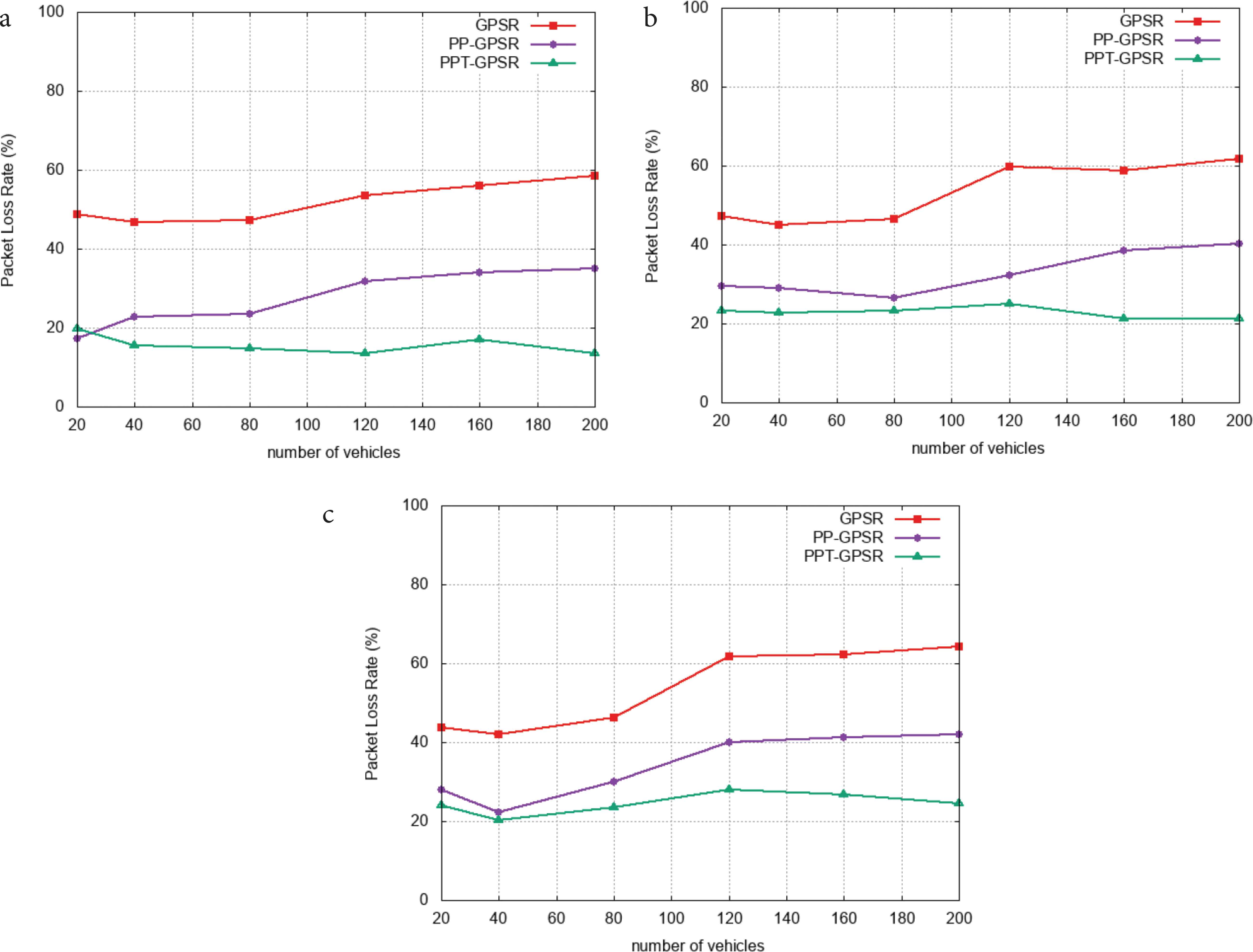
Packet loss rate vs. number of vehicles. (a) Beacon interval = 0.5 s. (b) Beacon interval = 3 s. (c) Beacon interval = 5 s.
Similarly, Packet Loss rate increases with the number of connections (Figure 6) and PPT-GPSR offers the lowest packet loss rates. The difference in rates, in some cases, exceeds 45% compared to GPSR loss rates and reaches 20% compared to PP-GPSR loss rates.
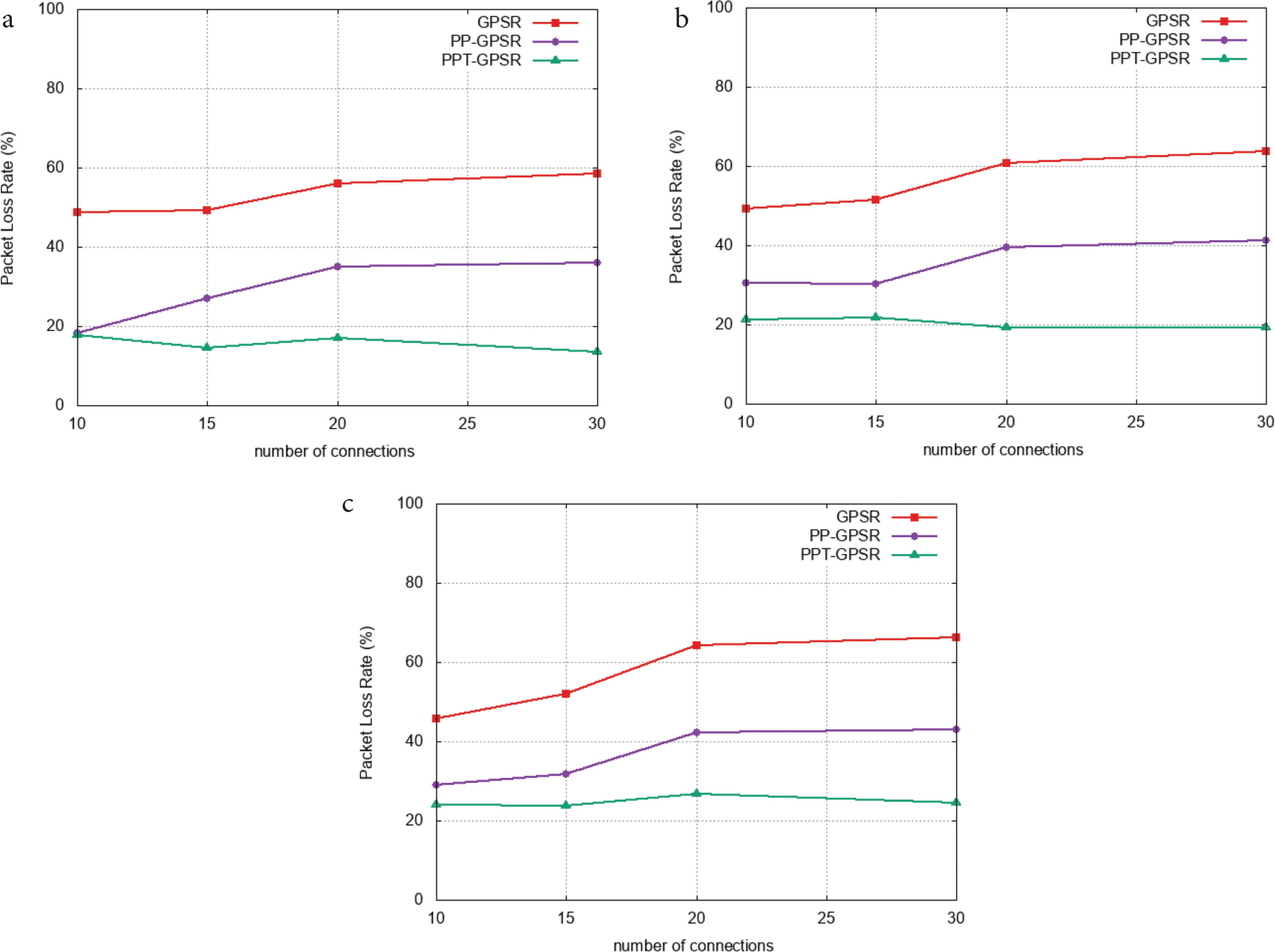
Packet loss rate vs. number of connections. (a) Beacon interval = 0.5 s. (b) Beacon interval = 3 s. (c) Beacon interval = 5 s.
It is quite normal that overhead routing increases with the number of vehicles. From Figure 7, we can see that the PPT-GPSR solution presents much better results than the PP-GPSR and GPSR.
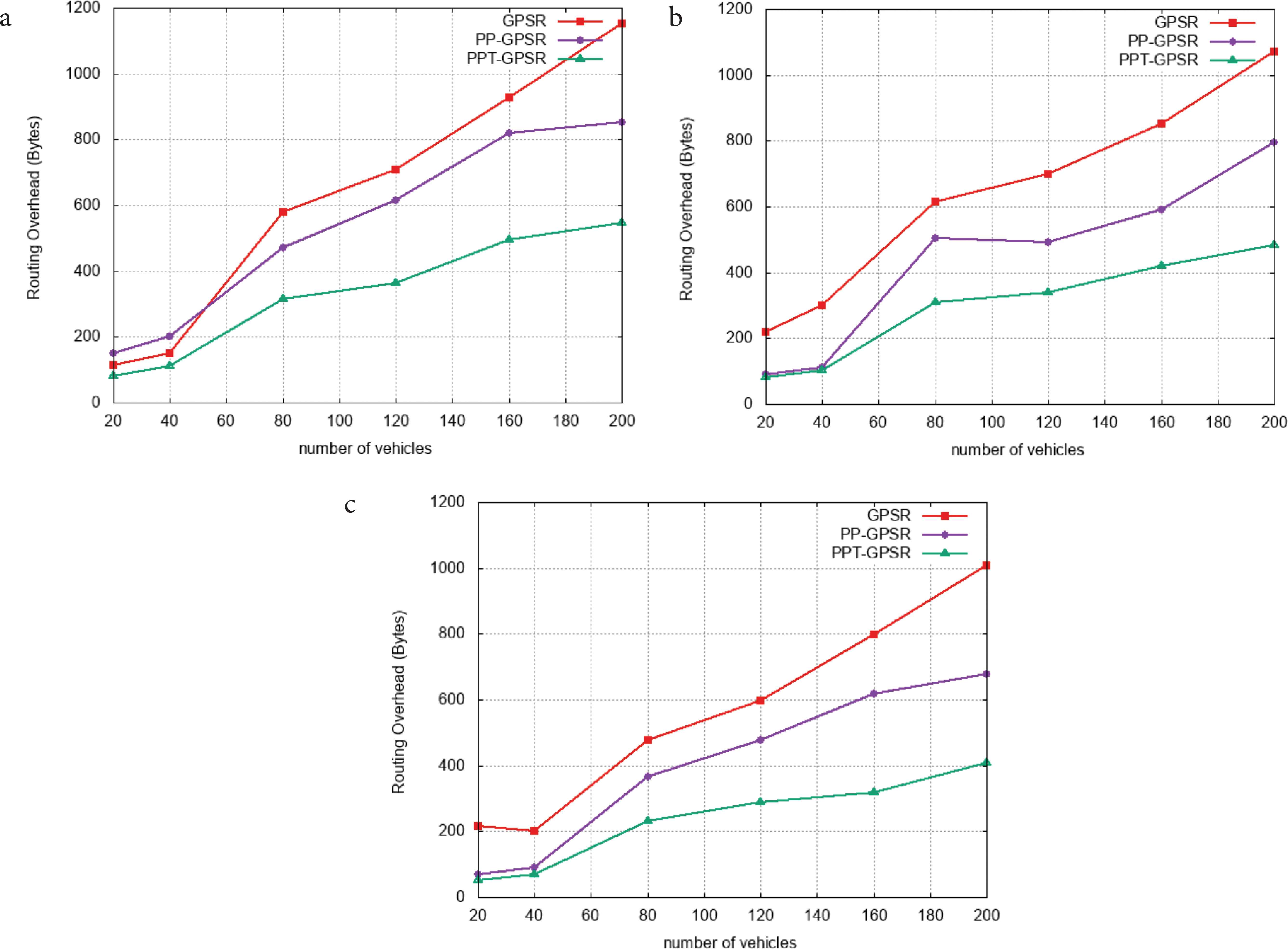
Routing overhead VS number of vehicles. (a) Beacon interval = 0.5 s. (b) Beacon interval = 3 s. (c) Beacon interval = 5 s.
Using the notion of threshold; average path length vs. number of vehicles (Figure 8) shows that PPT-GPSR gains on average one hop compared to PP-GPSR. This gain reaches an average of three hops compared to GPSR.
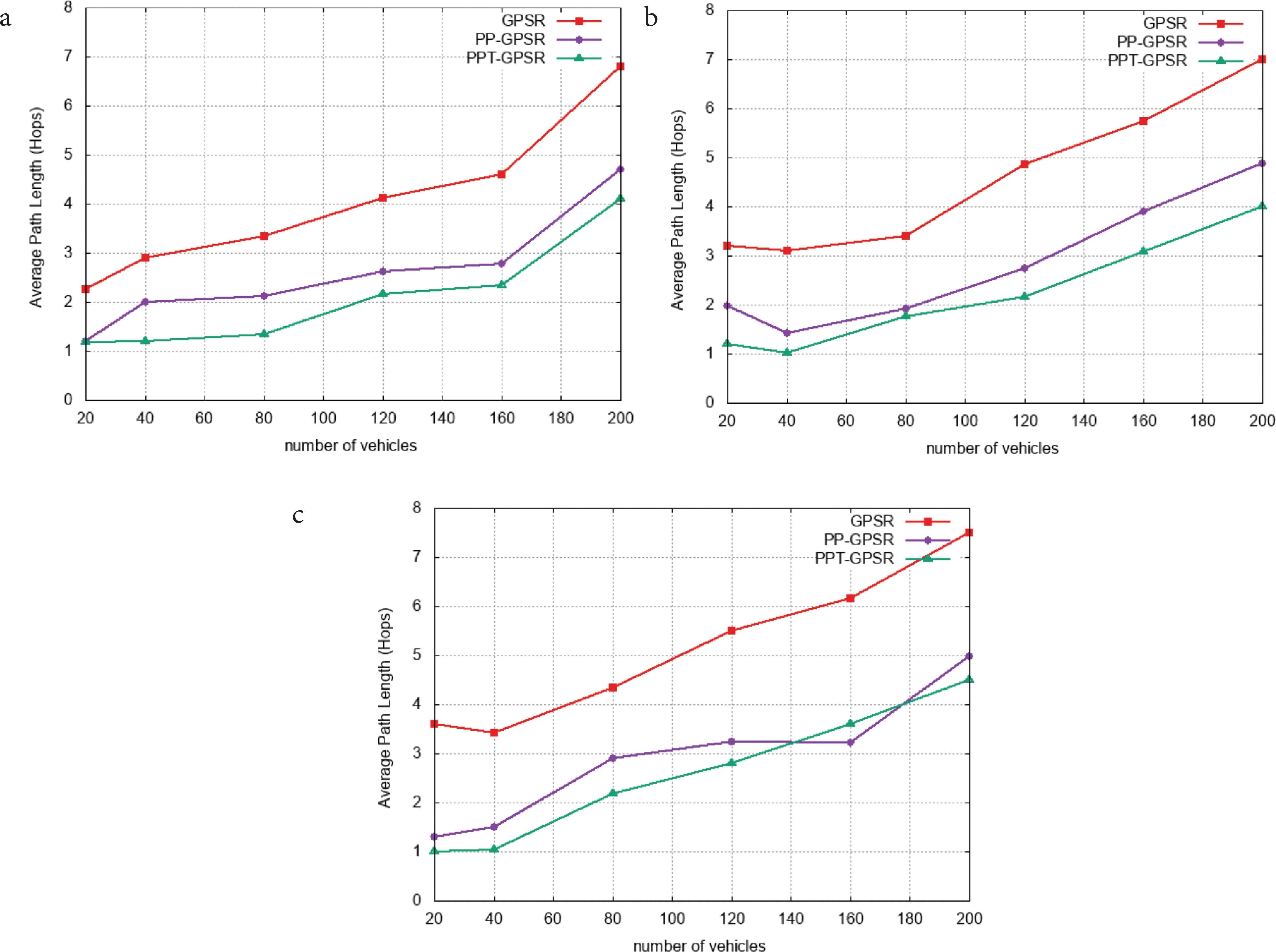
Average path length vs. number of vehicles. (a) Beacon interval = 0.5 s. (b) Beacon interval = 3 s. (c) Beacon interval = 5 s.
Finally, Figure 9 illustrates end to end delay vs. number of vehicles. The end-to-end delay decreases as the number of vehicles increases because there is a much “shorter way” to the destination. We constate that the PPT-GPSR solution offers better delays regardless of the number of vehicles, with an average gain of 100–250% (depending on the beacon interface) in transit time compared to GPSR, and this gain can be as much as 60% compared to the delays recorded by PP-GPSR.
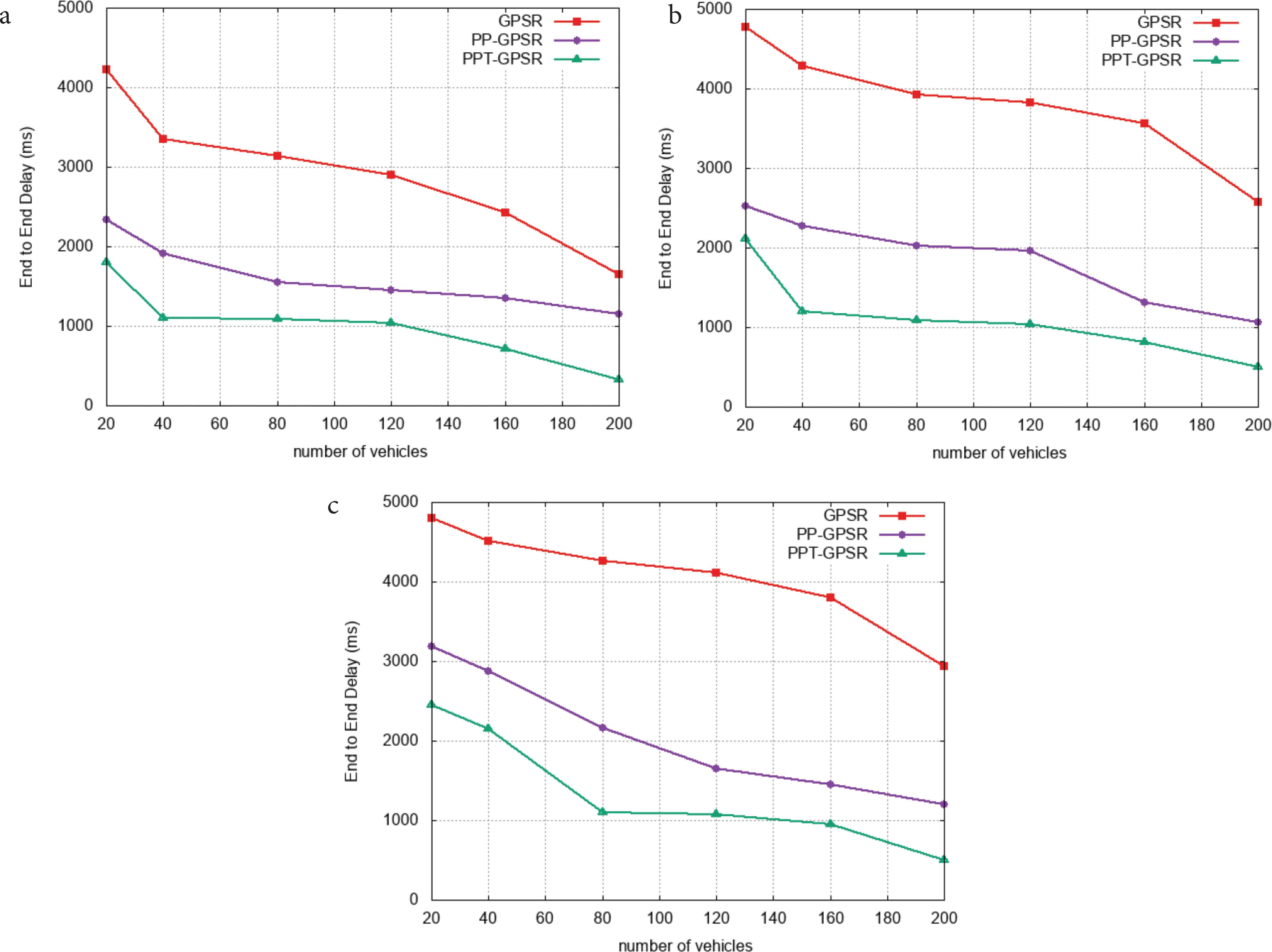
End-to-end delay vs. number of vehicles. (a) Beacon interval = 0.5 s. (b) Beacon interval = 3 s. (c) Beacon interval = 5 s.
6. CONCLUSION
Due to the highly dynamic topology of VANETs, predicting vehicle mobility (change of geographical location) plays a key role in the design of efficient communication protocols. Indeed, in this paper we proposed the PPT-GPSR protocol that computes the predictive distance between each neighbor and the destination based on the future position of each node and a coverage limitation threshold. This solution guarantees optimal selection of the best next hop closer to the destination while avoiding disconnection and link failure. The contribution of our approach resides in the simplicity of design and the preserved identity of the original GPSR protocol. Results under several scenarios showed that the PPT-GPSR solution offers the best performance. However, we believe that with a 5 s interval beacon the results are largely satisfactory, although with 3 s in some scenarios the results are satisfactory. As a result, the work presented allows us to further improve the routing process, making it tolerant to link failure, which leads to higher packet loss rates and higher end-to-end delays. In our future work, we will present an approach based on a multi-criteria analytical model for link failure tolerant routing, the approach is currently being validated.
CONFLICTS OF INTEREST
The authors declare they have no conflicts of interest.
AUTHORS’ CONTRIBUTION
IC and ZMM contributed to the design and implementation of the research, to the analysis of the results and to the writing of the manuscript.
ACKNOWLEDGMENT
This research was supported by the
Footnotes
REFERENCES
Cite this article
TY  - JOUR
AU  - Ikram Cherifi
AU  - Zoulikha Mekkakia Maaza
PY  - 2021
DA  - 2021/07/12
TI  - Link Failure Tolerant GPSR Protocol
JO  - International Journal of Networked and Distributed Computing
SP  - 94
EP  - 104
VL  - 9
IS  - 2-3
SN  - 2211-7946
UR  - https://doi.org/10.2991/ijndc.k.210628.001
DO  - 10.2991/ijndc.k.210628.001
ID  - Cherifi2021
ER  -