
Enhancement of Copper Wire Lengthening Automatic System using Contactless Heater
- DOI
- 10.2991/ijndc.k.191115.002How to use a DOI?
- Keywords
- Copper wire; contactless heater; human machine interface (HMI); PLC; gripper
- Abstract
Copper wire can be elongated to a very thin size like 0.01 mm from an original 0.6 mm via wire drawing dies. Although automatic machines are available for wire elongating process, the wire threading through dies still requires a human operation before entering an automation process. This procedure may repeat up to tens of times to complete, taking a long time. To resolve this problem, this paper develops an adjustable automatic wire copper wire drawing system for elongation using contactless heater. Three pneumatic claws are designed in the proposed system. The first claw is used to clamp the wire. The second claw fixed in the rotating mechanism is to draw the heated wire. The third claw is used to move the wire going through the drawing die after the drawn wire is cut off in one side. Then, the wire will be drawn again through the die mold. The force amount for drawing the wire can be adjusted via the gear connection controlled by the serer motor. Therefore, the system can be suited for variety of copper wire sizes. The experimental results prove that the proposed system has achieved the automatic copper wire elongation process successfully. Also, the human loading can be reduced considerably, and more importantly the operation time can be decreased significantly.
- Copyright
- © 2019 The Authors. Published by Atlantis Press SARL.
- Open Access
- This is an open access article distributed under the CC BY-NC 4.0 license (http://creativecommons.org/licenses/by-nc/4.0/).
1. INTRODUCTION
Copper wire is the most widely used conduction material to carry a variety of signals. Its applications include a large power transportation in power systems, or small signal communication in electronic devices or produces. The copper wire size can be as small as 0.01 mm, particularly in medical health equipments. Presently, many kinds of automatic wire drawing machines are being applied in industry. However, the copper wire needs heating, being drawn and then going through and drawing die mold by human hands when the automatic wire elongation process starts.
Currently, various functionalities required in industry have made the automation system extremely varied. For this reason, the modern automation systems are moving toward very high complexity, depending on the system structure [1–6]. Unfortunately, it is found that the copper wire elongation system for threading through the die mold is not completely automated so far in industry. Recently, an automatic copper wire elongation system was reported in the literature [7,8]. The proposed technique was based on three pneumatic grippers combined with the ring drawing machine for elongation process. However, it was only suitable for a soft copper wire rather than a hard material. Accordingly, it still has a difficulty for further applications [9–12].
2. SYSTEM STRUCTURE
2.1. Fundamental Concept
The torque required to pull the copper wire is designed based on the relation between the torque and gear ratio, shown in Figure 1 [7,8].
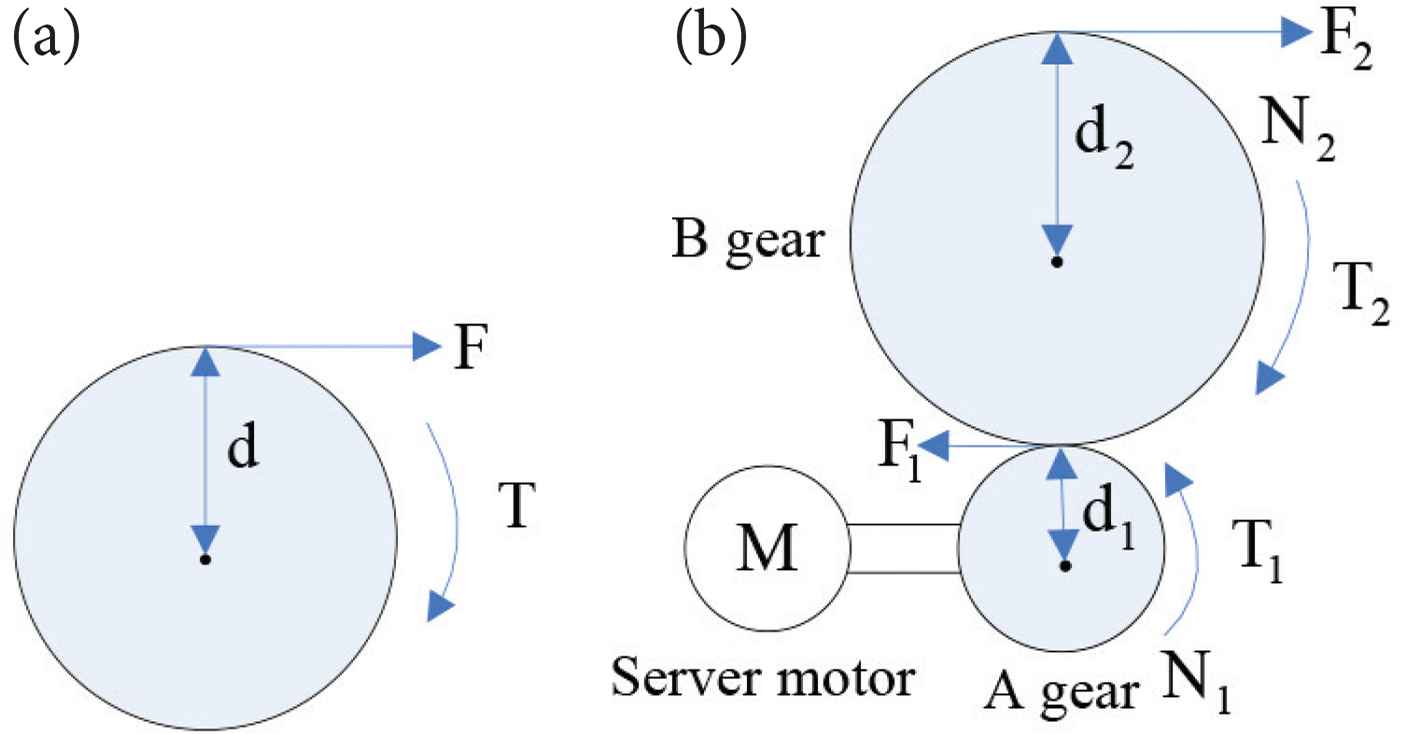
Relation of torque and gear [7]. (a) Torque. (b) Torque and gear.
In Figure 1(a), the torque is defined as [Equation (1)]
In Figure 1(b), the Gear ratio is [Equation (2)]
Torque ratio is [Equation (3)]
The power from the motor is transferred to the gears A and B equally [Equation (4)].
In the proposed system, N2 > N1 is designed to achieve T2 > T1 and thus F2 is enlarged. A gear used module: 1.25, tooth number: 30; B gear module: 1.25, tooth number: 150.
2.2. Design of System Hardware
The proposed system shown in Figure 2 mainly contains: (1) Copper reel provides copper wire for elongation. (2) Contactless heater is used to soft the copper wire. (3) Actuator contains pneumatic cylinder, server motor, grippers, pneumatic shear, slide table, etc. (4) Ring drawing machine is used to lengthen and elongate the copper wire. (5) PLC works as the control core. (6) Human Machine Interface panel provides users to operate the system.
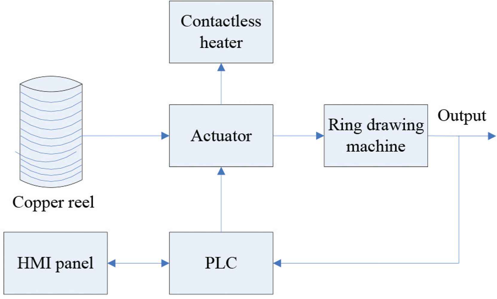
System structure.
The system mechanical organization is shown in Figure 3. It includes: (A) Gripper 1. (B) Gripper 2. (C) Contactless heater. (D) Gripper 3. (E) Pneumatic shear. (F) Gripper 4. (G) Ring drawing machine.
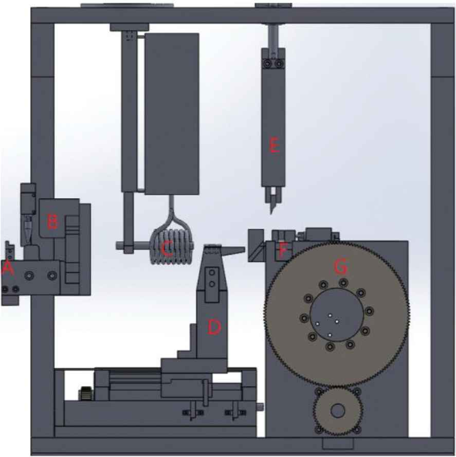
System mechanical organization.
3. THE SYSTEM OPERATION PROCEDURES
The proposed system is carried out by the following steps:
Step 1: The wire is pulled close to Gripper 4 through the contactless heater, as shown in Figure 4.
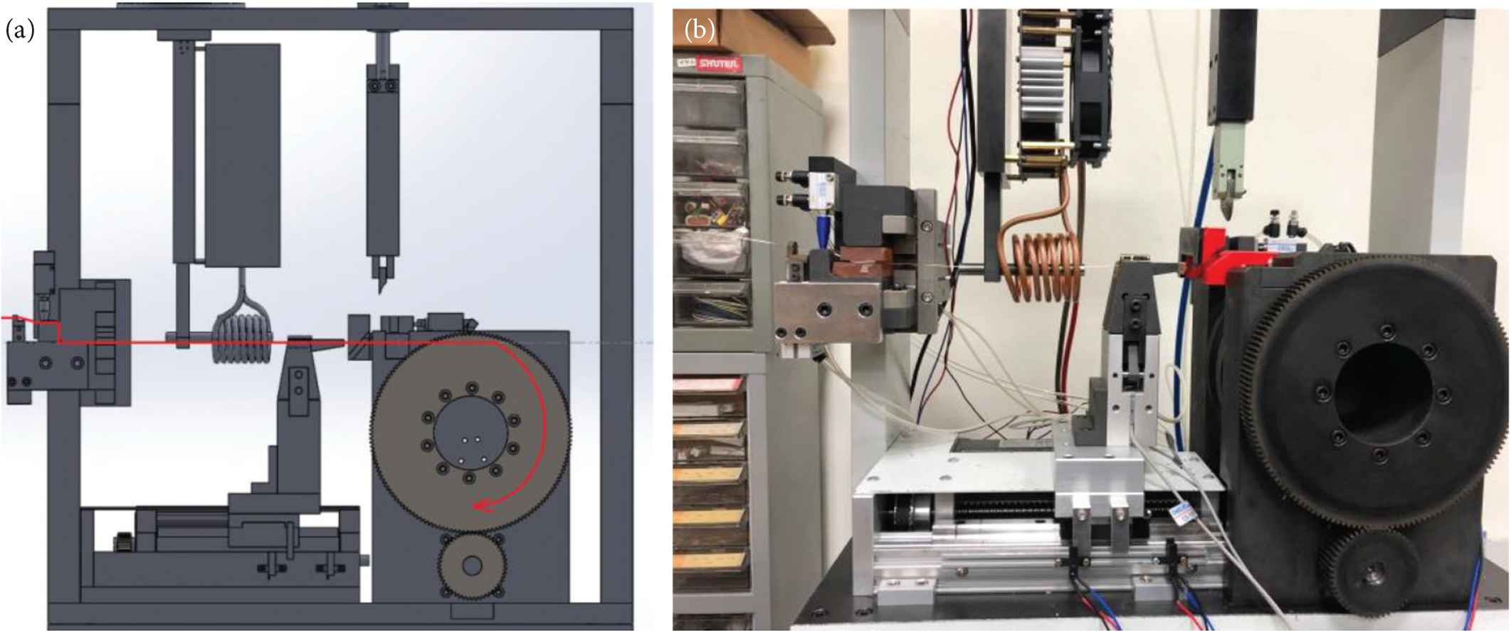 Figure 4
Wire pulling by Gripper 4. (a) Schematic diagram. (b) Entity profile.
Step 2: The wire is clamped by Grippers 1, 2 and 4 simultaneously, as shown in Figure 5. The heater starts to work until the preset temperature is reached.
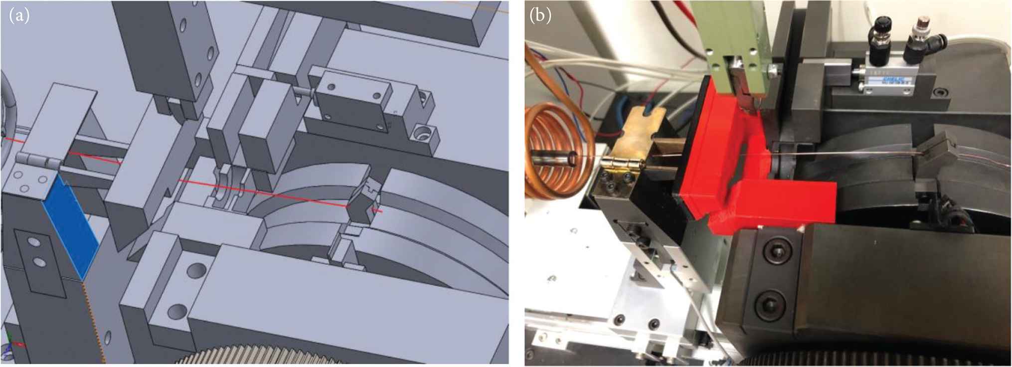 Figure 5
Heating process. (a) Schematic diagram. (b) Entity profile.
Step 3: The heating process stops, and then the lengthening process begins to work until the desired length is reached, as shown in Figure 6.
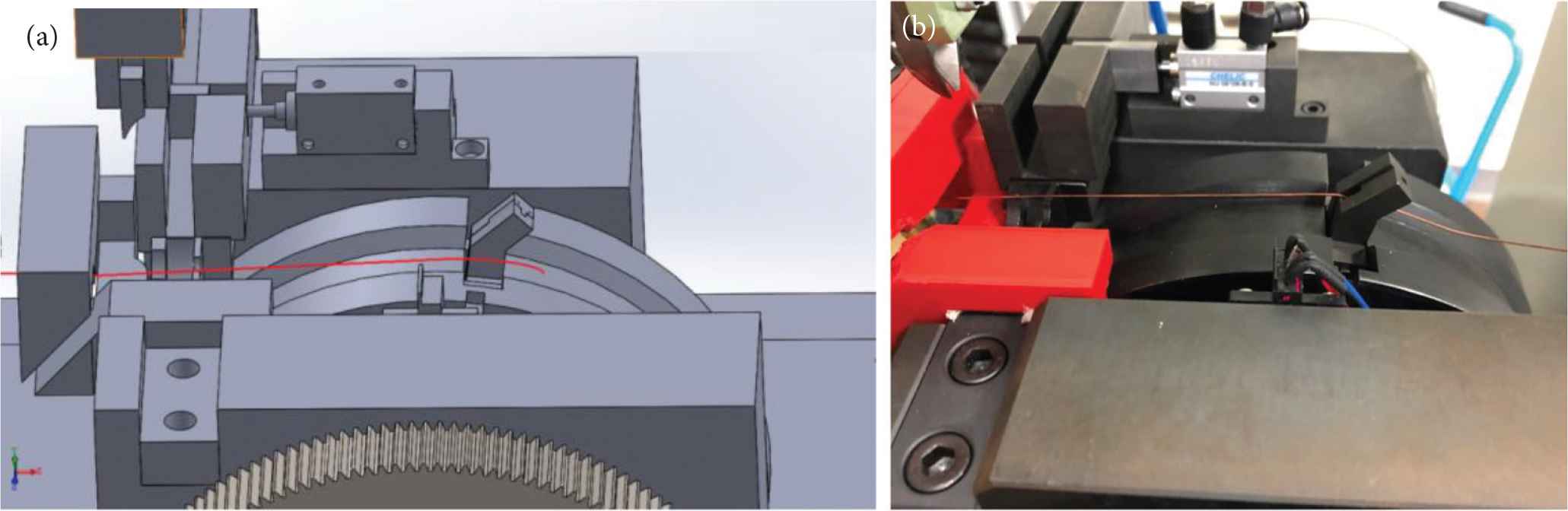 Figure 6
Lengthening process. (a) Schematic diagram. (b) Entity profile.
Step 4: The grippers 1 and 2 are opened, as shown in Figure 7.
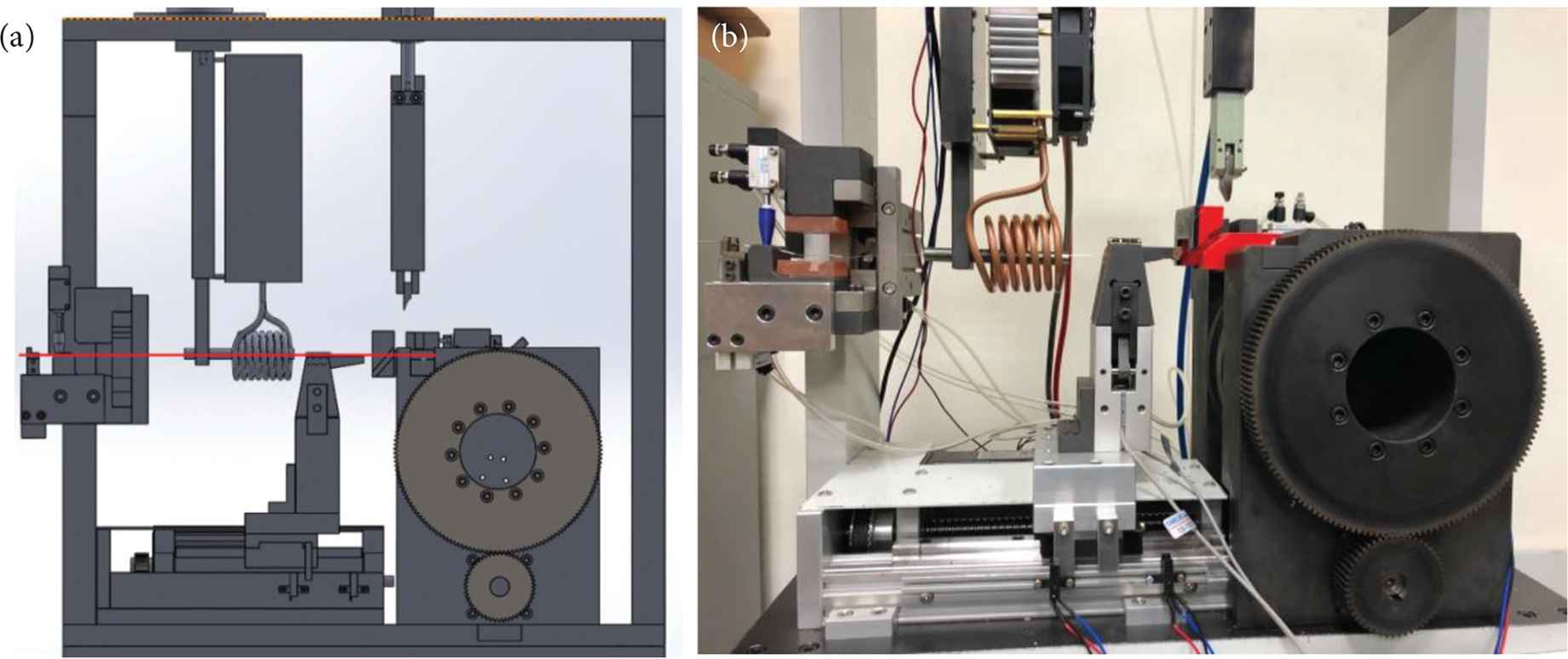 Figure 7
The grippers 1 and 2 opened process. (a) Schematic diagram. (b) Entity profile.
Step 5: The pulled slender wire is delivered to below the pneumatic shear by the ring drawing machine, as shown in Figure 8.
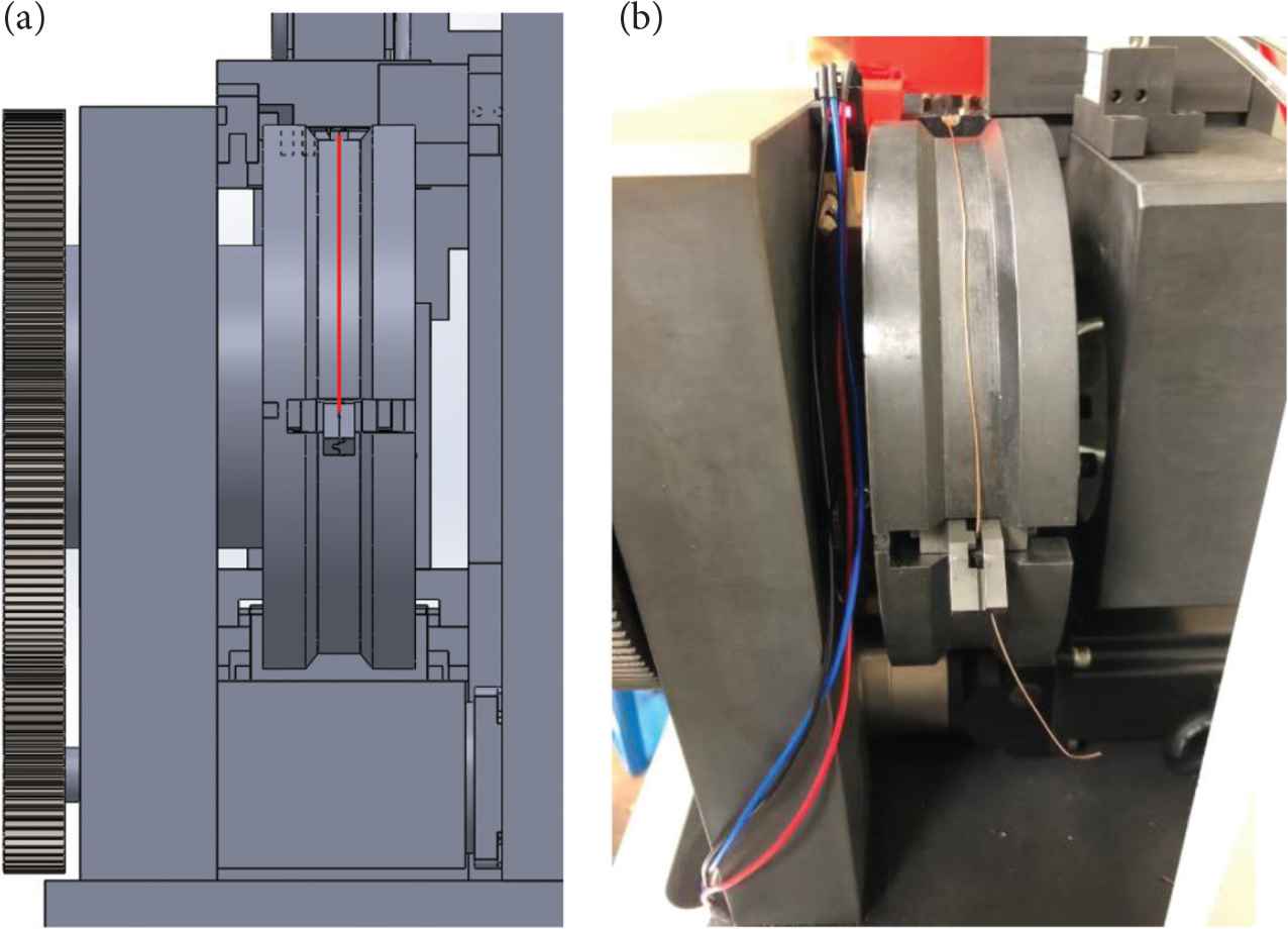 Figure 8
The pulled slender wire delivery. (a) Schematic diagram. (b) Entity profile.
Step 6: The wire is clamped by Grippers 2 and 3, and then it is cut out by the pneumatic shear, as shown in Figure 9.
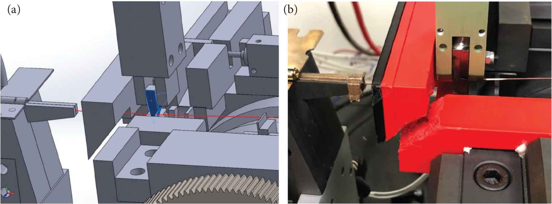 Figure 9
Wire cutting off process. (a) Schematic diagram. (b) Entity profile.
Step 7: The die mold moves down to the holder for wire threading process, as shown in Figure 10.
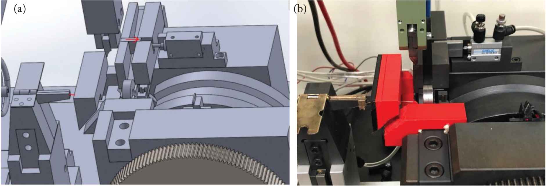 Figure 10
The die mold moving process. (a) Schematic diagram. (b) Entity profile.
Step 8: The Gripper 1 is opened, and then the Gripper 3 clamps the wire to thread through the die mold, as shown in Figure 11.
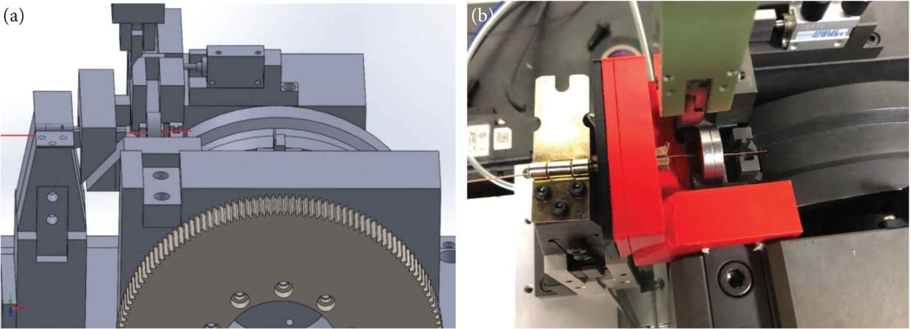 Figure 11
The die mold threading process. (a) Schematic diagram. (b) Entity profile.
Step 9: The Gripper 3 is opened, and then the Gripper 4 clamps the wire to move forward using the ring drawing machine, as shown in Figure 12.
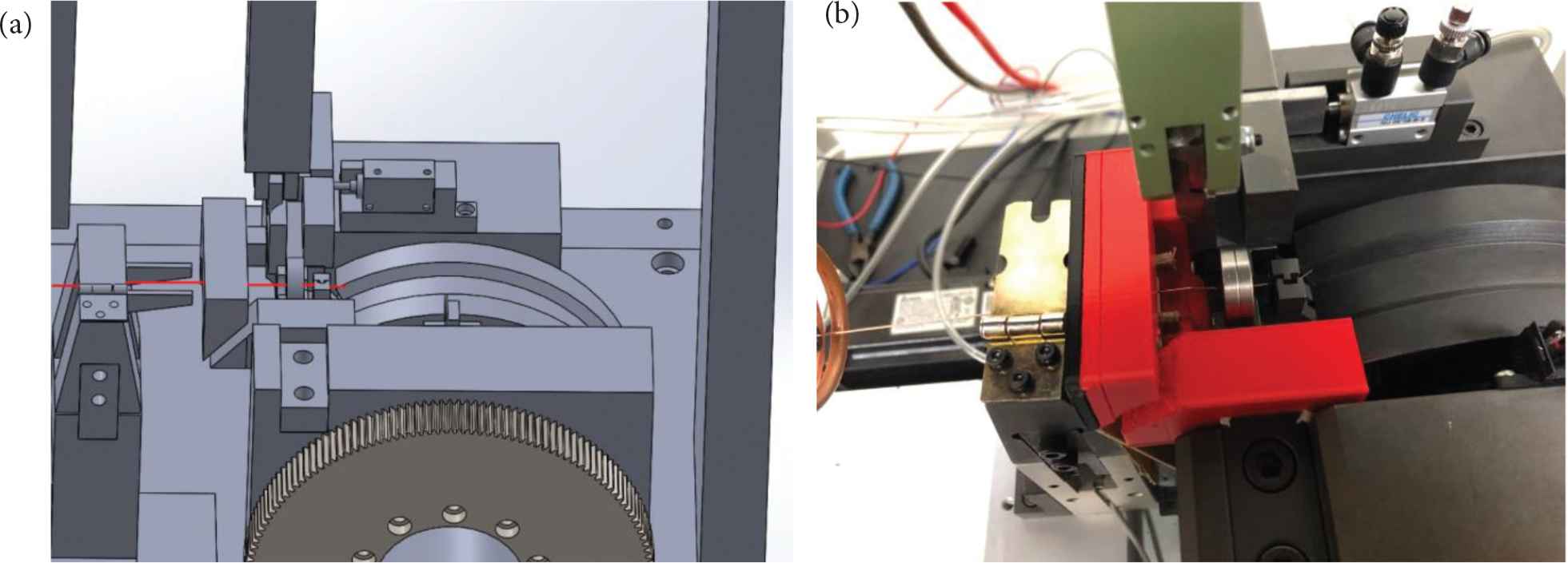 Figure 12
The wire elongation process. (a) Schematic diagram. (b) Entity profile.
Step 10: The wire is pulled forward until reaching the desired length, as shown in Figure 13.
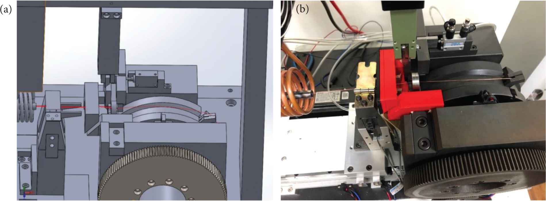 Figure 13
Accomplishment of the wire elongation. (a) Schematic diagram. (b) Entity profile.
4. EXPERIMENTAL RESULTS
The experiments were carried out under the room temperature at 24°C before heating. When the heating starts from 0 s to 20 s, the copper wire heated temperature rises from 24°C to 497°C almost linearly over the heating time, as shown in Figure 14.
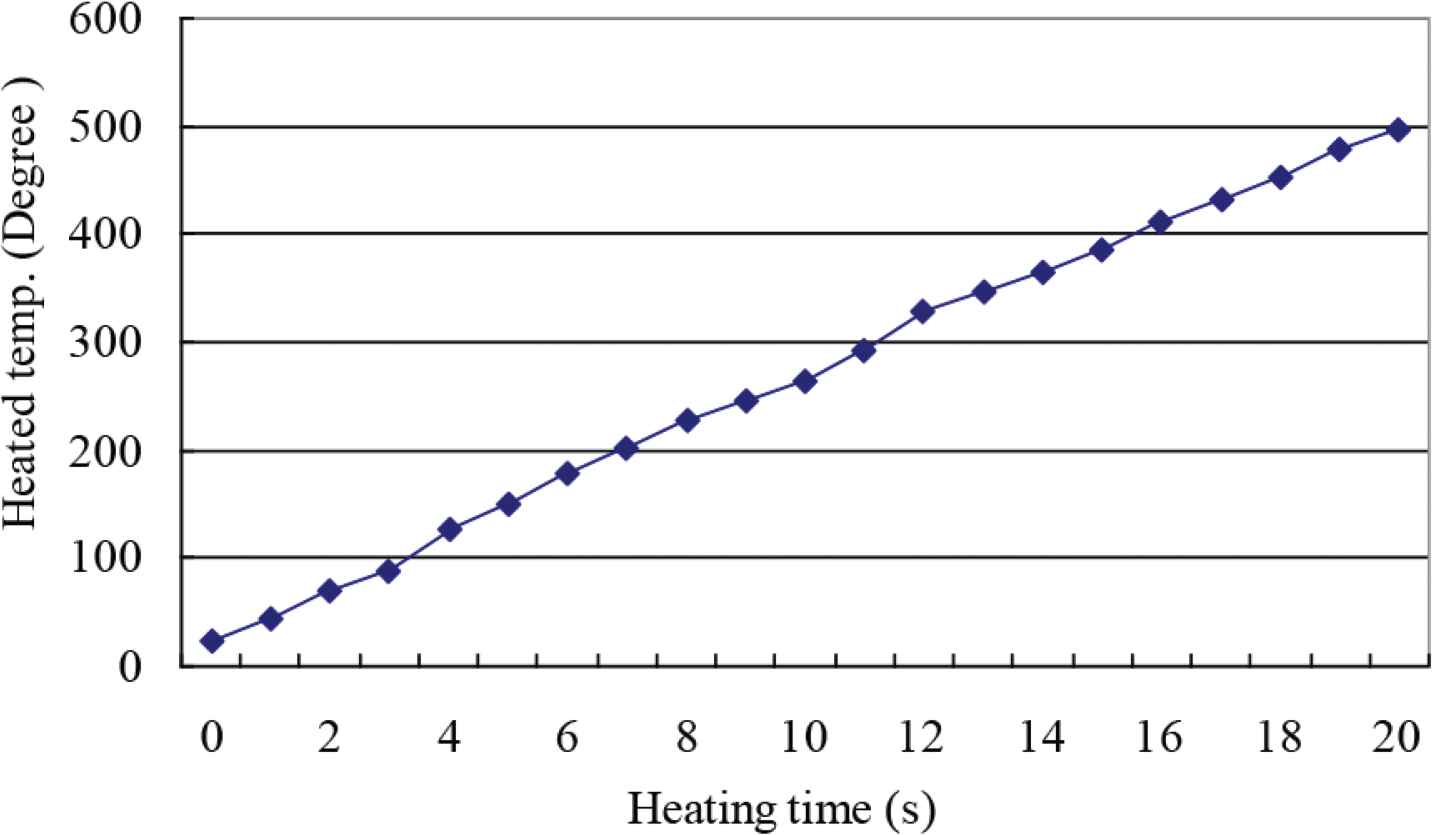
Heating temperature vs. heating time.
The pulled length over the heating period between 12 s and 18 s under the wire pulling speed: k1 (1.86 m/s) is shown in Figure 15. Note that the heating time below 12 s is found insufficient to soften the copper wire so that it fails to pull the wire. On the other hand, the heating time beyond 18 s, the copper wire heated temperature is higher than 478°C. This causes the copper wire carbonization, and it is thus unsuitable for elongation. Moreover, it is noted that the wire slender length required for threading through the die mold must be longer than 30 mm in this system. For this reason, the experimental results reveal that the heating period between 14 s at 365°C and 18 s at 452°C can be satisfactory.
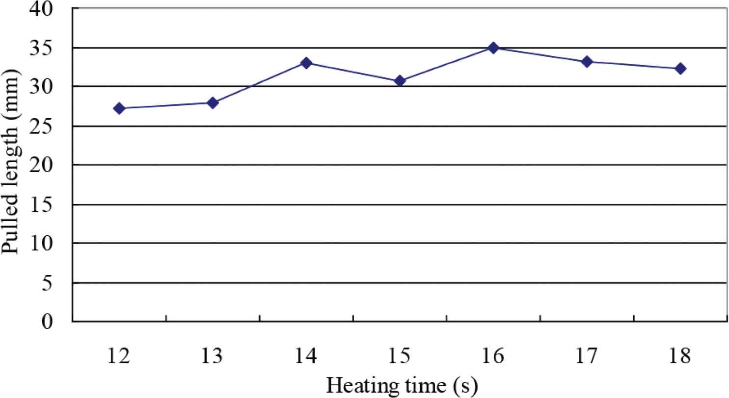
Pulled length vs. heating time at k1 speed.
The experimental results using the wire pulling speed: k2 (3.78 mm/s) under the same condition as above is shown in Figure 16. It is found that only the heating time between 12 s and 14 s can achieve the desired length (≥30 mm) for elongation purpose. It reveals that higher pulling speed may reduce the pulled length considerably.
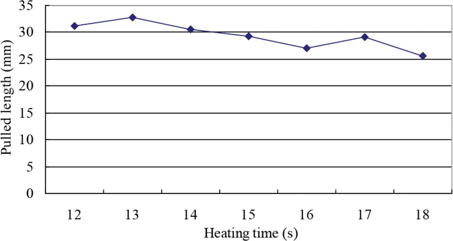
Pulled length vs. heating time at k2 speed.
5. CONCLUSION
This paper has successfully designed a copper wire lengthening automatic system using contactless heater, which can replace a human operation and increase the machine working efficacy. Additionally, the proposed system can be combined with the existing machines directly without changing the mechanism of machines. Some more achievements can be reached:
- (a)
It is suitable for various copper wire sizes and materials.
- (b)
Wire elongation length can be adjusted using PLC programming.
- (c)
Human-interface machine can provide a friendly monitoring and control functions for users.
- (d)
Wire drawing speed is adjustable.
- (e)
Contactless heater can soft the copper wire for lengthening and elongation appropriately.
Moreover, the experimental results imply that the wire elongation is sensitive to the heated temperature and pulling speed. The wire pulling speed may be chosen as fast as possible. In contrast, a higher speed may risk a wire breaking during the elongation process.
CONFLICTS OF INTEREST
The authors declare they have no conflicts of interest.
ACKNOWLEDGMENT
The authors are grateful to Ministry of Science and Technology, Taiwan, for sponsoring the project: MOST 107-2637-E-167-002.
REFERENCES
Cite this article
TY  - JOUR
AU  - Hsiung-Cheng Lin
AU  - Jhih-Yao Hu
AU  - Chung-Hao Cheng
PY  - 2019
DA  - 2019/12/06
TI  - Enhancement of Copper Wire Lengthening Automatic System using Contactless Heater
JO  - International Journal of Networked and Distributed Computing
SP  - 9
EP  - 15
VL  - 8
IS  - 1
SN  - 2211-7946
UR  - https://doi.org/10.2991/ijndc.k.191115.002
DO  - 10.2991/ijndc.k.191115.002
ID  - Lin2019
ER  -