
Tracing a Weld Line using Artificial Neural Networks
- DOI
- 10.2991/ijndc.2018.6.4.4How to use a DOI?
- Keywords
- Robot; ANN; welding; image processing
- Abstract
Robotic manipulators are becoming increasingly popular nowadays with applications in almost every industry and production line. It is difficult but essential to create a common algorithm for the different types of manipulators present in today’s market so that automation can be achieved at a faster rate. This paper aims to present a real-time implementation of a method to control a Tal Brabo! Robotic manipulator to move along a given weld line in order to be utilized in factories for increasing production capacity and decreasing production time. The controller used here is provided by Trio, whose ActiveX component is interfaced to MATLAB. Images were captured to identify weld lines in every possible alignment to find points of interest and the neural network was trained in order to follow a given weld line once the work-piece was placed on the work-table.
- Copyright
- © 2018 The Authors. Published by Atlantis Press SARL.
- Open Access
- This is an open access article under the CC BY-NC license (http://creativecommons.org/licences/by-nc/4.0/).
1. INTRODUCTION
Robots are present in almost every industry with their applications ranging from simple pick-and-place to automated driving. Robotic manipulators are used in production lines where the productivity needs to be increased. With automation being implemented, high repeatability and precision can be ensured while minimizing the problem of fatigue and boredom [1]. When welding is carried out, high precision is needed to ensure that the weld stays along the line. This would require a good control strategy for the robotic manipulator such that the trajectory of the weld line is detected and followed with checks in place. Some of the advantages of using a robotic arm for welding are as follows:
- •
Increase in productivity: Robots are known to accomplish work at a rate faster than humans also having high repeatability. Having a greater arc-on time as compared to humans also increases output drastically in factories.
- •
High quality of work: A robotic welder will ensure that high accuracy is maintained at all times. Although workers are required for custom works, a highly repeatable welding task will be carried out with precision by the robotic welder reducing the need for a rework.
- •
Minimizing the distortion of weld joints: Distortion in weld occurs due to the continuously expanding and contracting of the weld and base metal. Robotic welders can easily identify the required size for the weld and reduce such distortions increasing quality and reducing errors.
- •
Safety: There are many risks that workers face while welding such as shock and exposure to toxic gases, which can be reduced by implementing a robotic welder.
Attempts have been made in the recent past to trace the weld line using a seam tracking sensor as discussed in Kam et al. [2]. Their paper describes a two-wheeled robot with a seam tracking sensor that is able to trace straight and curved lines with the help of potentiometer type sensors which produce an error signal. This method does not involve any vision control and depends entirely on the error signals to produce efficient results. Methods based purely on vision have also been implemented as described in Säntti et al. [3] where image processing using the Hough transform is carried out on a FPGA based camera to identify the seam for laser welding. This method, although provides little lag, is heavily dependent on the FPGA processing power. If a good frame rate is not ensured during the process, the tracking will deviate causing errors. To increase accuracy along with lesser dependence on processing power, an attempt has been made to implement the vision tracking system in conjunction with artificial neural networks (ANNs).
To track a weld line after identification, a method is required to map the real world points to the joint angles of the robotic manipulator. The Tal Brabo! Manipulator used here does not grant the users with access to view the inverse kinematics of the robotic arm, making it difficult to check whether the robot has reached the required destination. Although there are many methods available to choose from, ANNs were used. Also, working with a single camera eliminates the usage of analyzing the exact real world positions of the weld-piece. Usage of a stereo camera along with a depth sensor would have made it easier to produce a relationship between the position of the camera and the point of interest. Taking these limitations into consideration and after analysis of various methods, ANNs was chosen due to the following reasons [4,5]:
- •
Their ability to learn by example, making them flexible and powerful.
- •
Having no access to the inverse kinematics of the robotic manipulator limits our understanding of the internal mechanisms. Usage of ANNs bypasses this limitation.
- •
Artificial neural networks work best in detecting patterns too complex to be detected by humans or other computer techniques. The underlying pattern between the weld line and the joint angles can be easily identified when implementing an ANN.
Hough transform is generally used for feature and shape extraction in robotic vision systems to trace weld lines as discussed in Molina et al. [6]. To decrease the load on image processing, simple techniques such as conversion to gray-scale and filtering were used to identify the weld line. This decreases the computation time and the load on the processor while also simplifies the detection process.
Industrial robots need safety checks to ensure that they do not collide with the nearby equipment and humans. To ensure this, limits were introduced to ensure that the robot does not move across a given point.
The main objectives of the paper are as follows:
- •
To detect weld lines when placed in any alignment on a work table.
- •
To trace the weld-lines using a 5-DOF robotic manipulator.
Section 2 discusses the steps taken to interface the robot with MATLAB to ensure a smooth transfer of information to and from the controller. Section 3 explains the steps taken to detect the weld line using image processing whereas Section 4 describes the various neural network algorithms used for training and data collection. Section 5 validates the results and draws the conclusion to our given aim.
2. INTERFACING WITH THE ROBOTIC MANIPULATOR
To create an optimized system, it is necessary that information is passed on to the manipulator smoothly as well as with high speed and accuracy. MATLAB was identified as the perfect program for implementing our solution, having resources to process images as well as train neural networks. It was essential to interface the controller to MATLAB so that the end coordinates can be sent to the manipulator with ease.
The Trio motion controller is used here to control the motors of the manipulator. Having no accommodations for understanding the MATLAB program, ActiveX control was utilized to interface the robot to the controller [7].
ActiveX is a framework that can be embedded into almost every application and can understand all programming languages. An ActiveX window needed to be created and connection was needed to be established so that MATLAB could send coordinates to the manipulator for movement.
A Logitech webcam was placed in front of the work-table and connected to MATLAB in order to send and process images.
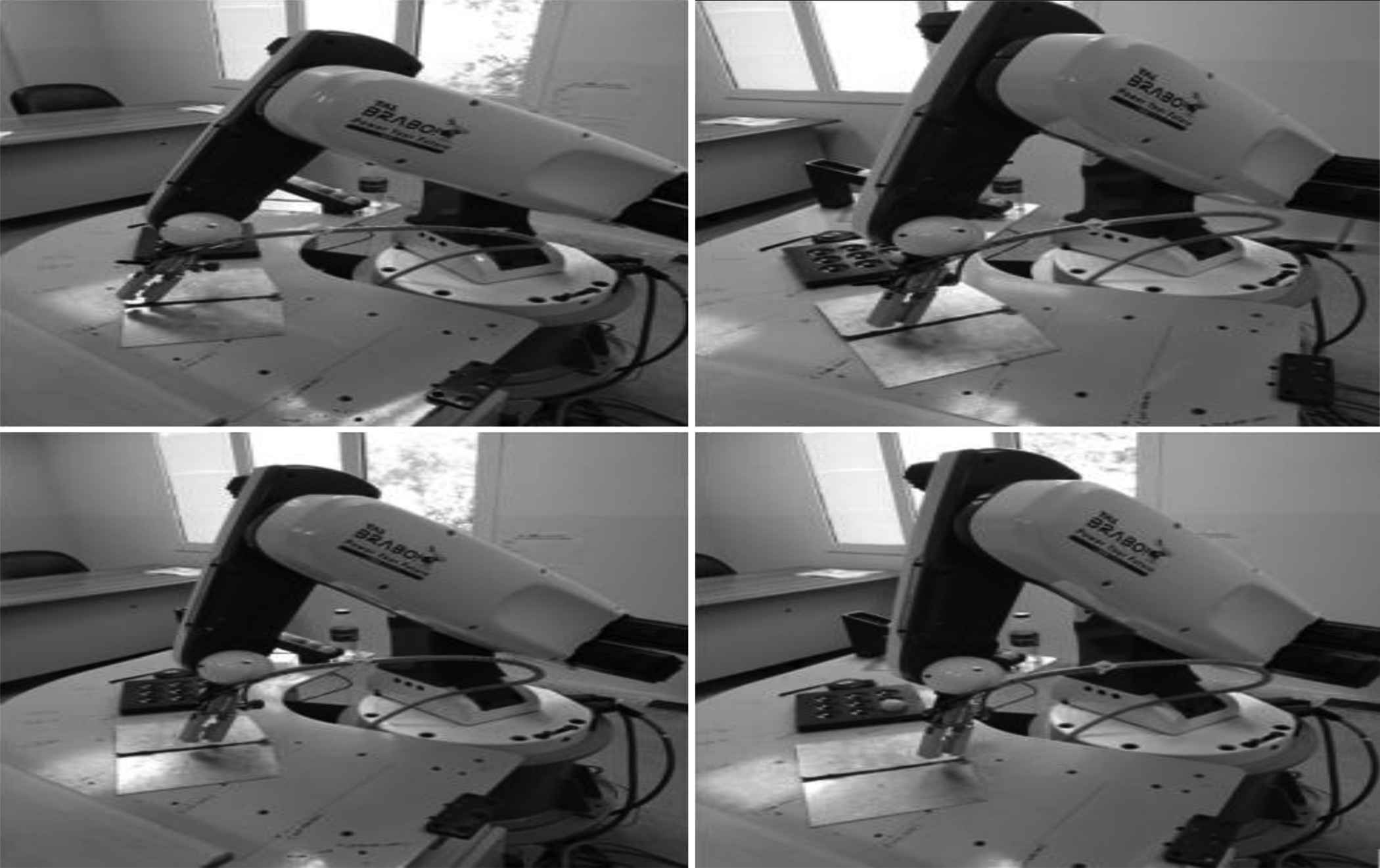
Figure 1 demonstrates the setup for carrying out the desired task.
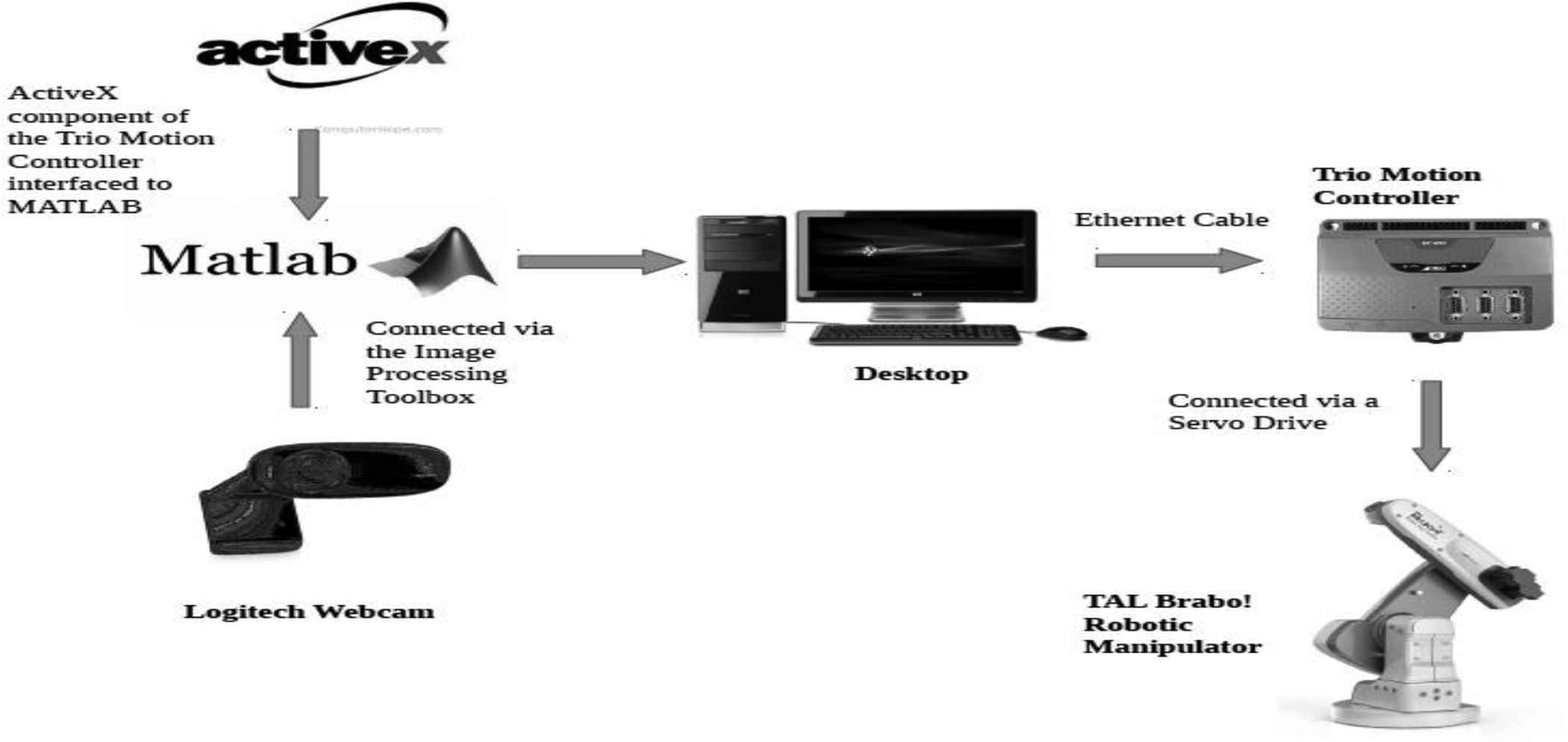
Interfacing diagram of the robotic manipulator
3. IMAGE PROCESSING FOR WELD LINE DETECTION
Operations on images were carried out to identify the weld lines and points of interest. Once identified, the pixel coordinates of the point were noted down to be fed into the neural network.
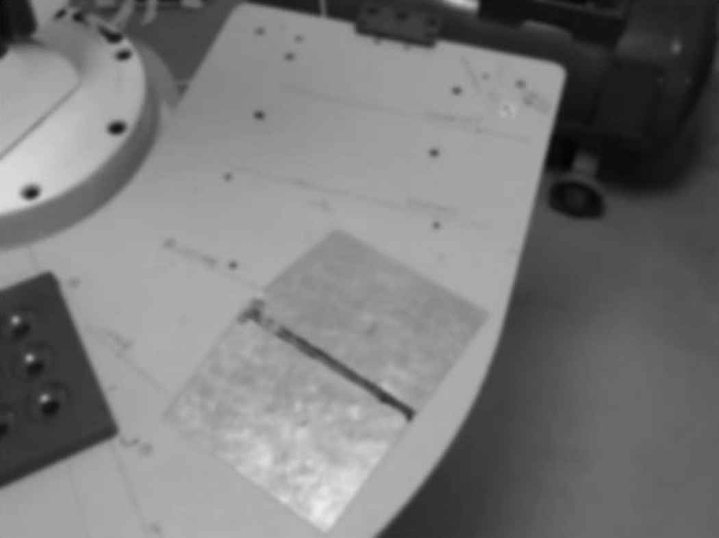
Images were captured using a Logitech Webcam -HD C310 with a resolution of 640 × 480 pixels so that the number of pixels required for processing was less as compared to its original resolution of 1280 × 720 pixels.
Certain preprocessing techniques were used to ensure that there were no disturbances when the weld line was detected.
- •
Lighting: The amount of lighting falling on the weld-piece had to be adequate when placed in any position, therefore the entire process was carried out indoors with sufficient lighting.
- •
Positioning: The camera was placed in a position such that it was able to visualize the entire work area. Any disturbance to its position or orientation will require the neural network to be trained again.
The sequence of various events in image processing is shown as a flowchart (Fig. 2).
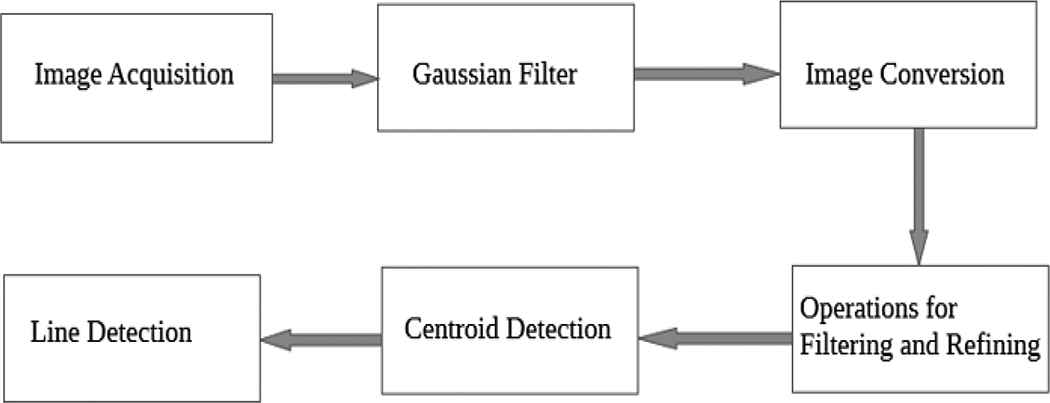
Sequence of image processing operations
3.1. Gaussian Filter
Gaussian filtering is a linear non-uniform low pass filter that is used in smoothing of images (Blurring) [8].
The 2-D Gaussian filter formula used in image processing is given in Equation (1):
‘σ’ represents the standard deviation. An increase in standard deviation leads to more blurring but is also restricted with the kernel size.
Here, the standard deviation is considered to be 0.447 according to our lighting and requirements.
The Gaussian filter does not generally preserve edges as compared to the median filter but was preferred for two reasons:
- •
Faster computation time due to the separability property of the filter.
- •
Easier threshold as compared to other filters.
The use of this filter eradicates the need for any edge detectors. The previously used
3.2. Conversion to Grayscale
The original image is captured in a resolution of 640 × 480 pixels 3 channel RGB (Red, Green, and Blue) converting to grayscale. This reduces both the computational energy required while also making segmentation far easier as the range of numbers are reduced drastically.
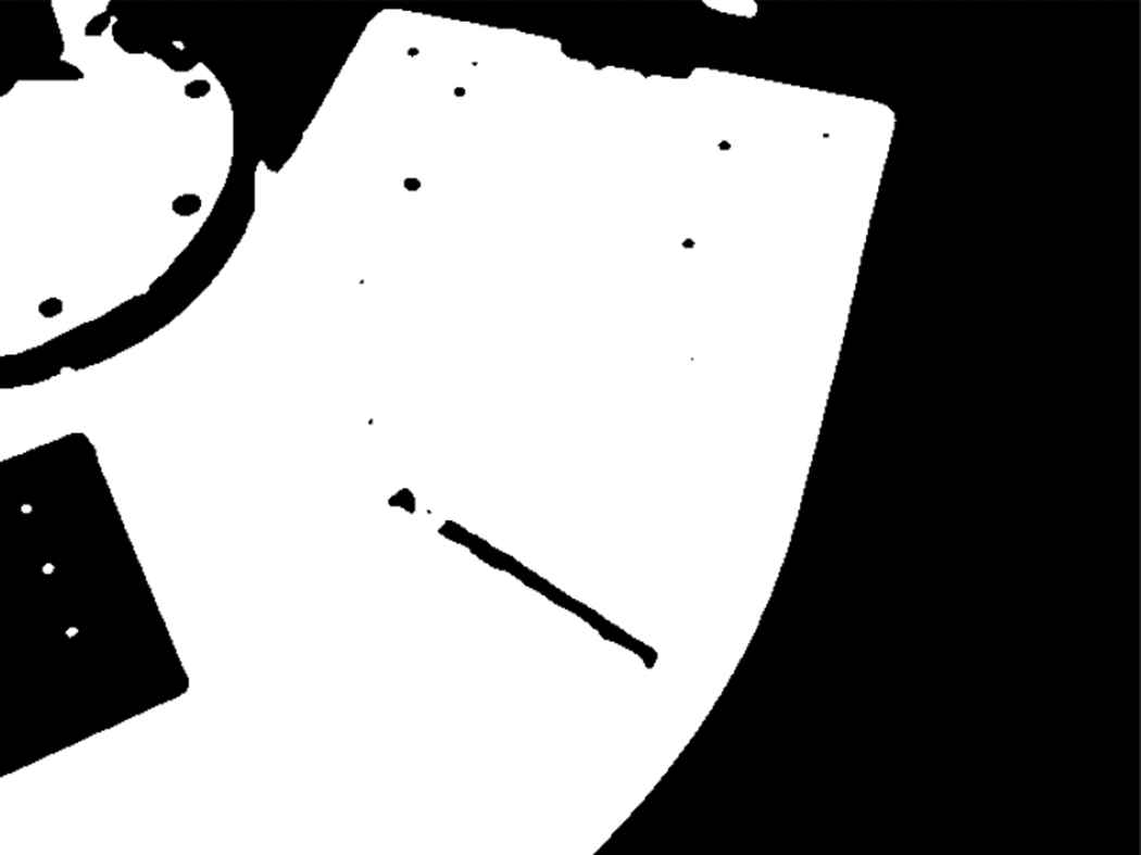
3.3. Binarizing and Complementing the Image
Binarizing converts the grayscale image matrix values into 0s and 1s making it easier to threshold. Once the image was binarized, it was observed that the weld line was considered to be a 0 (black). In order to process this line as the region of interest, the image was complemented.
3.4. Centroid Detection
The centroid of the region of interest, which is the weld line was identified to use as data in training. Once the centroid data is identified, it can be fed this into the neural network so that the algorithm learns to move to any identified point.
Figures 3–6 depict the image processing operations as stated before.

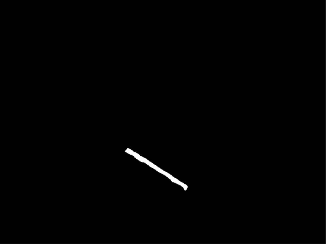
Raw image
Gaussian blurred image
Conversion to binary
Complementing and removing noise
3.5. Skeletonization
After the centroid was identified, the skeleton of the region was used to identify the weld line. The process of skeletonization successively erodes the boundaries of the image until no more erosion is possible. This leaves us with the skeleton [9] (the line). Figure 7 shows the skeleton of the weld line.
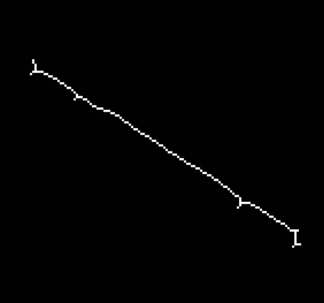
Skeleton of the weld line
3.6. Decomposition of the Weld Line
After the weld line was identified and singled out, the endpoints were taken and the points were generated in fixed intervals between the start and the end. The start position used to vary according to the given placement and orientation of the weld piece. These points were fed into the neural network to get the output once the training has been completed as they act as centroids for the robotic manipulator to move to.
4. NEURAL NETWORK TRAINING
Neural networks are computational structures which consist of fundamental computational units called neurons. These networks have an ability of classification of the data according to the weights and biases of the neurons. The weights of the hidden layer are varied as per the backpropagation algorithm over numerous epochs in order to introduce various features which can successfully fit the data and aid in reduction of the error metric.
4.1. Data Set and Network Architecture
The pixel coordinates of the centroid were noted down after the image was captured, serving as the inputs to the neural network. To record the outputs of the network, the robot was manually moved to the point of interest, i.e., the centroid. Fifty different readings were taken by placing the work-piece in different orientations and positions, covering majority of the table on which the work-piece was placed. Twenty random images were considered as the testing data. To ensure that there were no human errors, the resolution and the position of the camera, lighting and airflow were kept constant. A neural network architecture with two input neurons, ten neurons in the hidden layer and three output neurons was considered. The network architecture used for analysis is given in Fig. 8.
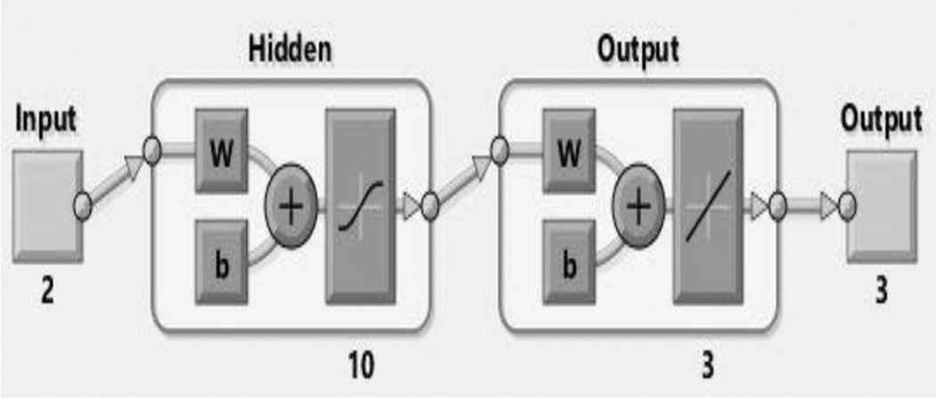
Neural network architecture for mapping weld points to pixels
4.2. Methodology
To compare and identify the method that produces the best accuracy and precision when moving the robot to the weld point, three different methods were chosen, namely the Levenberg–Marquardt, Scaled Conjugate Gradient (SCG) and the Bayesian Regularization (BR). These three methods were trained using the neural network fitting tool available in MATLAB. The input values for the neural network include the (x, y) coordinates obtained as endpoints of the weld-line from the image after the image processing steps.
The neural network maps these input values to the output values of the neural network, which are the (x, y, z) coordinates of the end effector of the robot in the joint mode. With these provided coordinates, the end effector can move to the endpoints of the weld work-piece. These forward kinematic solutions were experimentally verified in real-time by moving the Tata Tal Brabo robot to the various positions obtained as output from the neural network.
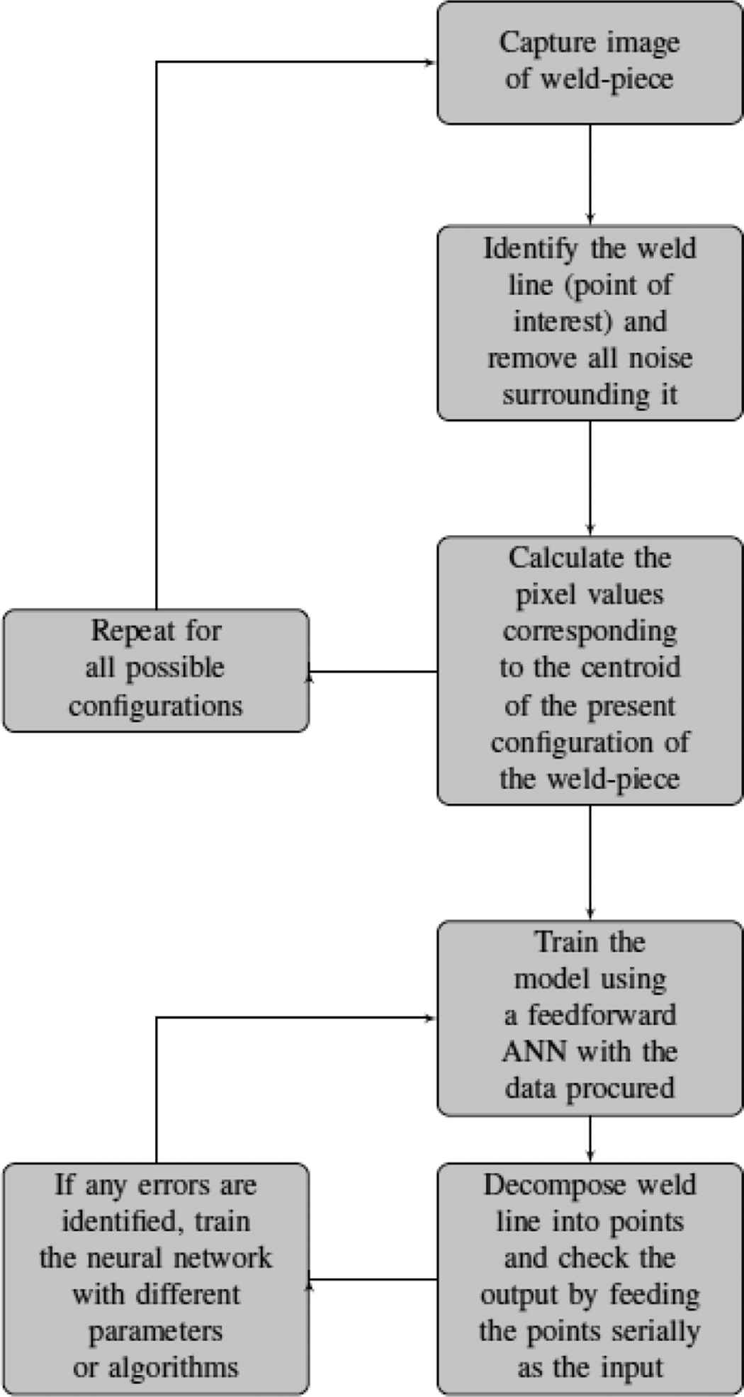
The figure below describes the steps taken to identify weld lines and train the robot to trace the line.
5. RESULTS AND DISCUSSION
To maintain consistency and verify the best method through which the training produces the test results, all the parameters of the neural network were kept constant. The parameters were chosen after testing with various samples. The input layer has two neurons, namely the x- and y-coordinate of the pixel at the specific point of interest. The output layer contains three neurons which provide us with the final positions of the three joints. The hidden layer started with five neurons and was increased till an acceptable answer was produced by the network. The neural network parameters used for training to detect the weld line are given in Table 1.
| Name | Value |
|---|---|
| Input layer | 2 |
| Hidden layer | 10 |
| Output layer | 3 |
| Training ratio | 55 |
| Validation ratio | 35 |
| Test ratio | 10 |
Neural network parameters
5.1. Training using Different Methods
The neural network was trained with three algorithms which include Levenberg–Marquardt (LM), SCG and BR [10,11]. Levenberg–Marquardt [12] took the least time to converge amongst when compared to all the three methods as shown in Figs. 9–11. Table 2 summarizes the various parameters.
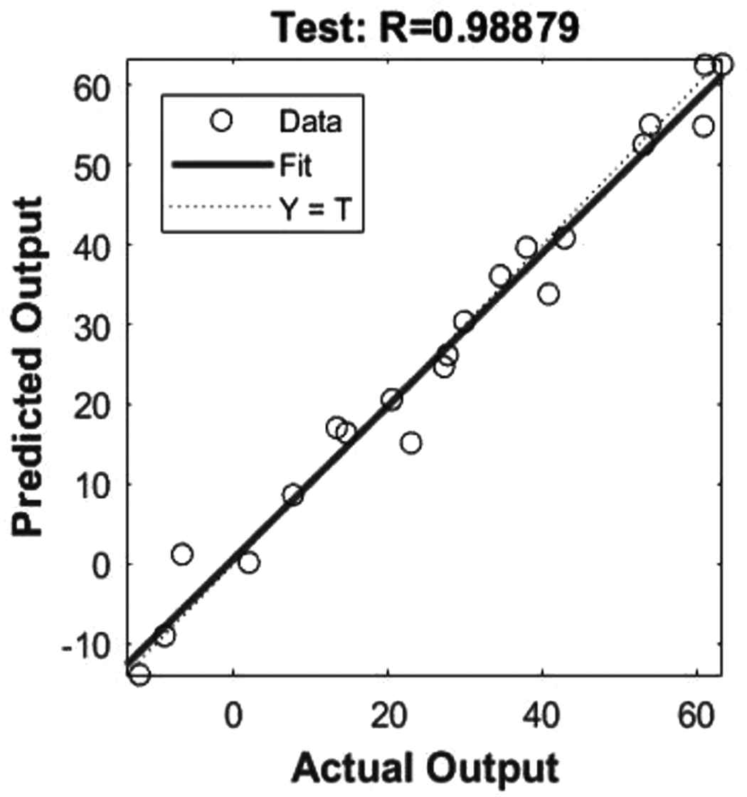
Scaled Conjugate Gradient method
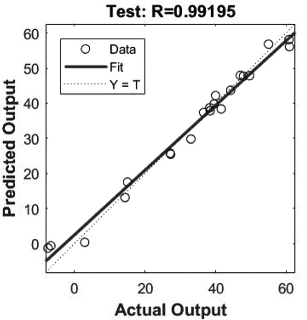
Levenberg–Marquardt method
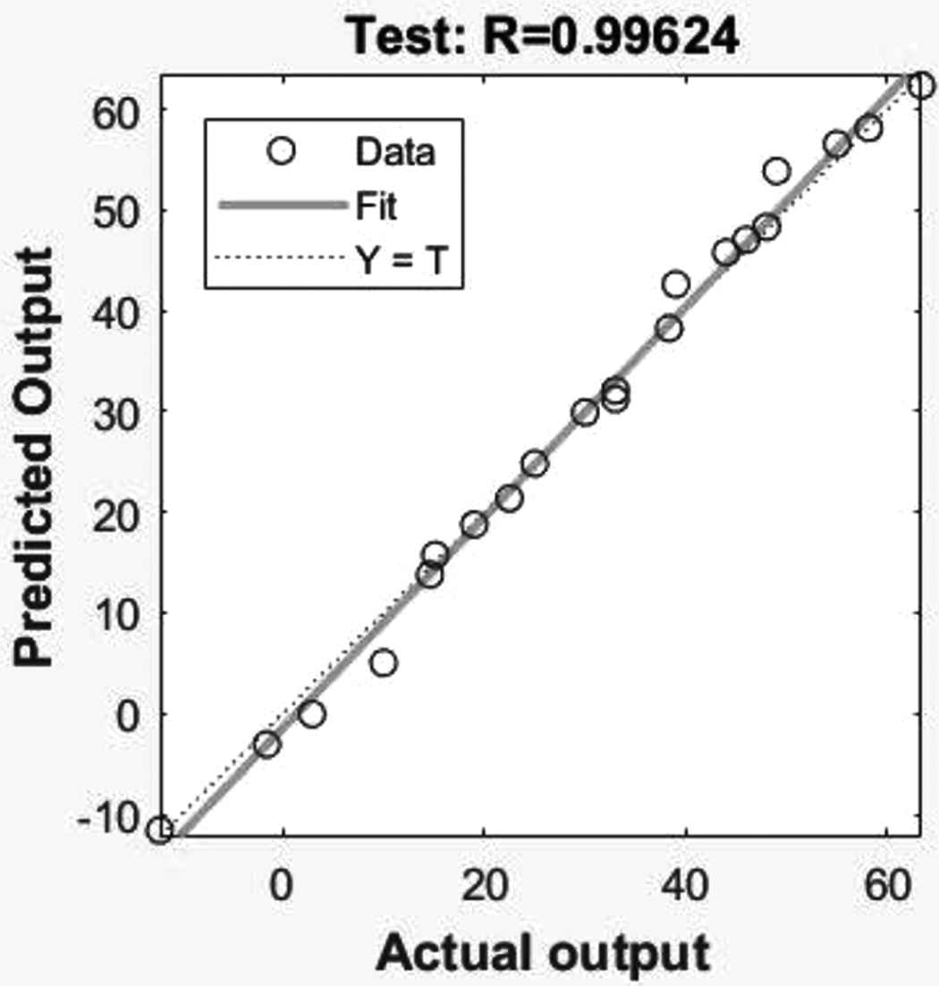
Bayesian regulation method
| Name | Number of Epochs |
|---|---|
| Levenberg–Marquardt | 12 |
| Scaled Conjugate Gradient | 23 |
| Bayesian regulation | 591 |
Comparison between various parameters
A fixed training/testing ratio of 55/45 [13] was taken for testing all the algorithms. When an attempt was made to fit the actual output with the predicted using all the algorithms used, it was noticed that the Bayesian regulation algorithm produced the best results. This algorithm passed through more data points than the other two methods. Although the line fitting analysis gave enough information about the efficiency of the algorithms, more information was needed to identify the algorithm that worked best in real-time systems.
Therefore, the testing data of 25 samples was run through the neural network through the various algorithms and the absolute difference between the ideal position and the position moved to was recorded for each sample and averaged. This was then tabulated and analyzed. The results are displayed below. The errors are displayed in centimeters as shown in Fig. 12.
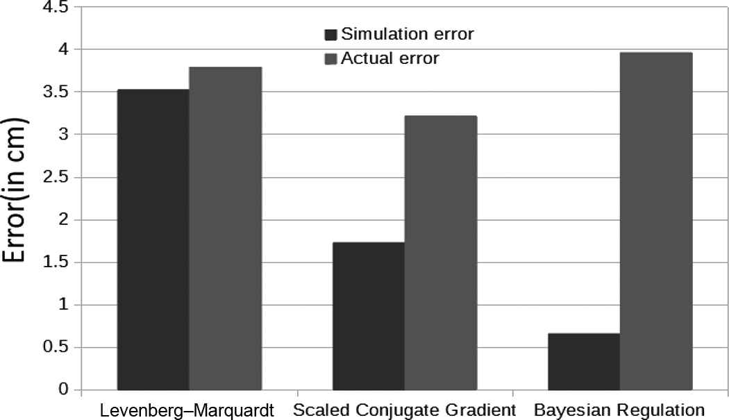
Error analysis
It is observed that even though the BR displays the least error when tested with the trained data, it fails to produce the best results when tested with unknown data. Although the Levenberg–Marquardt method converged in the least time and the BR method produced the least error with trained data, the SCG method was identified to be the best when testing with real world data. The complete real-time implementation of the robot tracking the weld line is depicted in Fig. 13.
The complete real-time implementation of the robot tracking the weld line
5.2. Limitations of the Present Model
The current model will fail to function if one of the following is altered:
- •
Lighting: Change of light intensity causes shadows and reflections on the workpiece resulting in errors when binarizing the image and incorrect weld line detection.
- •
Position of camera: The camera needs to be constantly fixed at a certain position. Any alteration will require retraining of the neural network as the pixel coordinates from the image will change when the position of the camera changes.
6. CONCLUSION AND FUTURE SCOPE
In this paper the process of interfacing the Tal Brabo to MATLAB using ActiveX control has been demonstrated. The task of identifying weld lines when present in any alignment as well as moving a 5-DOF robotic manipulator toward the weld line using ANN models. The neural network performance was analyzed by tuning the network with the efficient performance parameters and the performance of the neural network was verified in real-time by testing the output values using a 5-DOF Tal Brabo robot. It can be concluded that the ANN modeling has given satisfactory results and can be used for real-time applications.
Although the results were satisfactory, there are a few limitations to this model. The position of the camera needs to be unchanged for this model to work making the model is static. To create a dynamic model, a depth sensor should be used along with a camera placed on the arm of the robot so that a relation can be established between the camera and the weld line [14]. In the present work, an attempt has been made by implementing ANN on a real-time system. This system does not involve any other sensors and is purely based on vision. The method proposed has been designed to reduce the load on the processors to produce faster outputs as well as lesser power consumption in comparison with the other methods used in the past, this proves to be both cost-effective and efficient.
6.1. Alternative Methods for Better Accuracy
Using a 3-D camera negates the usage of neural networks completely as we can easily calibrate the 3-D camera to correlate the pixel points to the weld line.
This would encompass the usage of a point cloud [15]. Point clouds are produced by 3-D cameras that output a set of data points in space.
The setup would be the same as the current one but would have the same limitations. Changing the position of the camera would require recalibration and lighting would play an important role too, this method, although would provide a better accuracy, it ends up costing a lot as 3-D cameras are not cheap.
Using an Adaptive Neuro Fuzzy Inference System (ANFIS) [16] would help produce a robust algorithm with fuzzy logic coming into play. ANFIS utilizes both neural networks and fuzzy logic taking the strengths from both of these methods.
References
Cite this article
TY  - JOUR
AU  - Srinath Hanumantha Rao
AU  - V. Kalaichelvi
AU  - R. Karthikeyan
PY  - 2018
DA  - 2018/09/28
TI  - Tracing a Weld Line using Artificial Neural Networks
JO  - International Journal of Networked and Distributed Computing
SP  - 216
EP  - 223
VL  - 6
IS  - 4
SN  - 2211-7946
UR  - https://doi.org/10.2991/ijndc.2018.6.4.4
DO  - 10.2991/ijndc.2018.6.4.4
ID  - Rao2018
ER  -